Select Sections to Plot
Icon: ![]()
![]()
Menu: Roads > Settings > Select Sections to Plot
Ribbon: Roads Tab > Plan Production Panel > Selected Sections
Introduction
During the design process, it is likely that more cross sections will need to be sampled than are required to plot or set out.
Use the Select Sections command to decide which sampled cross sections to use for:
- Setout
- Plotting
- Cross sections
- Long sections
- Surface modelling
- Volumes
This command is also available at the time of initiating a ![]() Long Section plot or
Long Section plot or ![]() Cross Section plot or
Cross Section plot or ![]() Setout of the data in the drawings
Setout of the data in the drawings
Details
This command enables the designer to control which sections of the Road (or Road Object) design is included in the different Outputs.
After starting the command, select an alignment from the drawing or press [Enter] to select from a list.
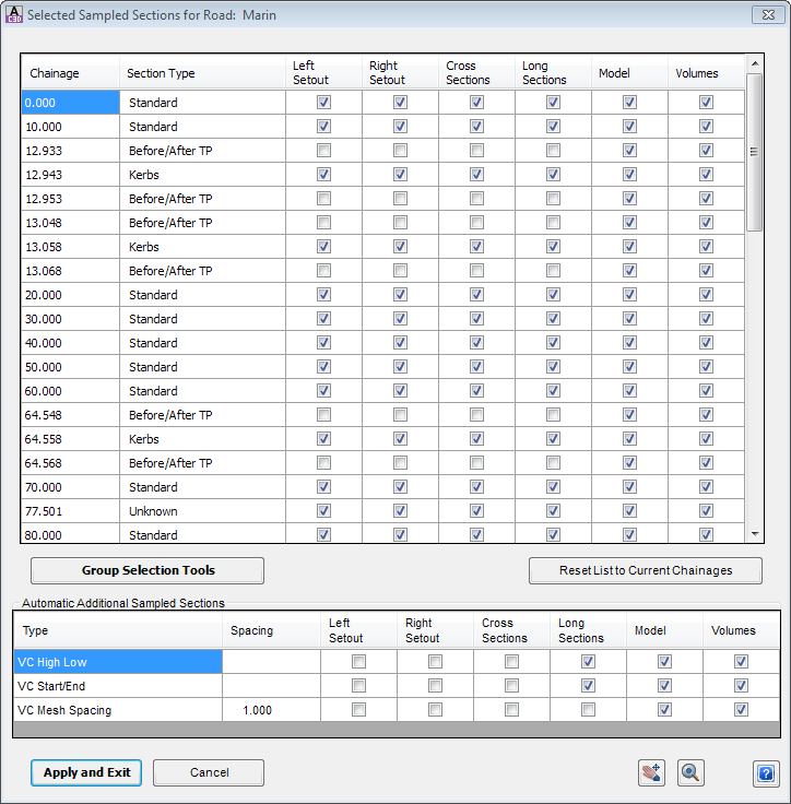
After selecting an alignment, the following form is displayed:
 |
|||||||||||||||||||||||||||||
| Top Form | This reports the Chainage and Type of section. Users toggle ON to include it in Left Setout, Right Setout, Cross Sections, Long Sections, Model or Volumes. | ||||||||||||||||||||||||||||
| Chainage | Indicates the location of the sampled chainage. | ||||||||||||||||||||||||||||
| Section Type | Lists the source of the chainage (where they come from):
|
||||||||||||||||||||||||||||
| Left Setout | Part of the |
||||||||||||||||||||||||||||
| Right Setout | Part of the |
||||||||||||||||||||||||||||
| Cross Sections | Part of the |
||||||||||||||||||||||||||||
| Long Sections | Part of the |
||||||||||||||||||||||||||||
| Model | Part of the Surface Modelling routines ( |
||||||||||||||||||||||||||||
| Volumes | Part of the |
||||||||||||||||||||||||||||
| Note: Clicking on a row will highlight it in the Drawing (a green line will display at the selected Chainage). | |||||||||||||||||||||||||||||
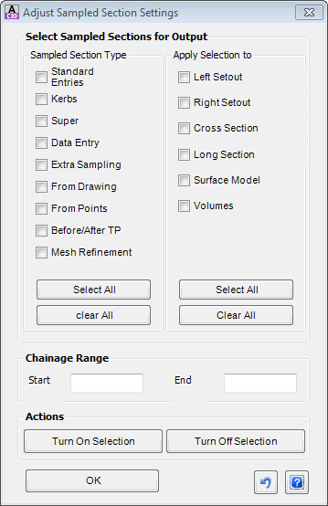
| Group Selection Tools | This command button enables group selection and control of the Outputs based on Section Type.
Click on the command button to open the form:
|
||||||||||||||||||||||||||||
| Reset List to Current Chainages | Click here to remove extra chainages that may have been included over time. Adding sampled sections in the Design Data Form and then removing them will not automatically clear them from the Selected Sections list. | ||||||||||||||||||||||||||||
| Automatic Additional Sampled Sections | This form enables inclusion of the Vertical Curve geometry points in the Outputs, as well as increasing the spacing of data through the vertical curves. | ||||||||||||||||||||||||||||
| VC High Low | Tick ON for the selected Outputs to include the calculated high and low points. | ||||||||||||||||||||||||||||
| VC Start/End | Tick ON for the selected Outputs to include the calculated start/end of vertical curves. | ||||||||||||||||||||||||||||
| VC Mesh Spacing | Type in a Spacing value and tick ON the selected Outputs to include extra sections between the Vertical Curve Start/End points at regular Spacings. | ||||||||||||||||||||||||||||
| Allows the user to zoom and free pan in the drawing. Press [esc] to return to the form. | |||||||||||||||||||||||||||||
| Centre the drawing at the highlighted chainage in the list | |||||||||||||||||||||||||||||
| Apply and Exit | Apply changes and exit the form. | ||||||||||||||||||||||||||||
| Cancel | Exit the form without applying changes. | ||||||||||||||||||||||||||||
Special Notes: The on/off toggle options for the different Types is initially read from the ![]() Active Drawing Settings - Cross Section Usage tab. The changes made to the Selected Sections is stored with the particular Road upon applying the changes and exiting the form.
Active Drawing Settings - Cross Section Usage tab. The changes made to the Selected Sections is stored with the particular Road upon applying the changes and exiting the form.