Auto Model
Icon: ![]()
![]()
Menu: Roads > Auto Model
Ribbon: Roads Tab > Modelling Panel > Auto Model
Introduction
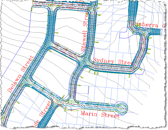
After using Civil Site Design to create the road network this command creates a single CSD surface of the entire road network, including all trimming at the intersections, cul-de-sacs, knuckles and roundabouts. This command can be initiated at any time during the design process, however it is recommended that you have created all the roads before running the command to ensure that the intersection trimming works as expected.
The new surface is called TotalModel and is stored as an CSD Surface (also known as an CSD Quick Surface in AutoCAD Civil 3D)
Depending on the settings, the TotalModel surface will automatically update as edits are made to any road network string.
Any CSD Surface (including TotalModel) can have it's display edited using the
![]() Create/Edit Surface
command.
Create/Edit Surface
command.
Layers used to display the surface object are managed by the
![]() Active Drawing Settings >
Layer Names Tab. The component layers used to display different
components of the surface (such as the major and minor contours) are managed via
the
Active Drawing Settings >
Layer Names Tab. The component layers used to display different
components of the surface (such as the major and minor contours) are managed via
the
![]() Create/Edit Surface
for CSD Surfaces and Civil 3D Styles for Civil 3D Surfaces.
Create/Edit Surface
for CSD Surfaces and Civil 3D Styles for Civil 3D Surfaces.
Civil 3D Users - Creating a Surface
A Civil 3D surface can be created for TotalModel (and any other CSD Surface) by using the
![]() Export CSD Surface
to Civil 3D command.
Export CSD Surface
to Civil 3D command.
Modelling Issues - Overlaps
CSD Surface
The CSD Surface boundary is automatically applied by locating the triangles that reside between the batter extents – all triangles outside of this are excluded. In the case of overlapping boundary lines, the software will ignore the overlaps and still apply a boundary. The CSD Surface can result in discontinuous roads triangulating across to each other. In these cases the Create/Edit Surface command should be used to either set a Maximum Triangle Length to remove the unnecessary triangles or Edit>Delete Line to manually trim away the excess triangulation.
Note: if alignments have direction changes that are not supported by horizontal curves, or if the design batters extend beyond the radial point of a horizontal curve, batter overlaps will result and impact on the boundary creation.
Civil 3D Surface
A Civil 3D surface can be created for TotalModel (and any other CSD Surface) by using the
![]() Export CSD Surface
to Civil 3D command.
Export CSD Surface
to Civil 3D command.
Note: Every Surface exported from CSD to Civil 3D will be given the same name as the CSD Surface with a prefix of C3D- (eg: the TotalModel Surface would be called C3D-TotalModel when exported to Civil 3D).
If the model does not include all kerb returns at an intersection, or if there are overlapping boundary strings, boundaries will not be correctly applied. Users can either address these modelling issues and re-apply the command, or manually adjust the boundary polyline/s that are outputted and add them to the Surface Definition. When overlaps are detected in the boundary, the polyline will be drawn but a boundary will not be applied (because Civil 3D does not allow boundary loops) - the designer can edit the boundary and apply it manually to the surface.
Stopping the Surface from Being Deleted and Recreated
All of the settings for the surface output are adopted from the
![]() Active Drawing Settings > Modelling Tab - if the
user doesn't want the software to delete and recreate the surface each time (and
instead simply remove and reinstate breaklines to the surface) then the option
to delete surface should be un-ticked. This relates to the Civil 3D
Surface export function only.
Active Drawing Settings > Modelling Tab - if the
user doesn't want the software to delete and recreate the surface each time (and
instead simply remove and reinstate breaklines to the surface) then the option
to delete surface should be un-ticked. This relates to the Civil 3D
Surface export function only.
Before Running Auto Model - Settings
The default output display for the Surface (whether an CSD Surface or a Civil 3D
Surface) is controlled from the
![]() Active Drawing Settings > Modelling Tab.
Active Drawing Settings > Modelling Tab.
Details
After running the command, the drawing will update to include a new surface. Surface Definition data will include breaklines.
Message reports will display to confirm the model output details, some of
which can be suppressed by adjusting settings in the
![]() Active Drawing Settings > Modelling Tab.
Active Drawing Settings > Modelling Tab.
Example outputs are as shown below:
 |