Compute & Apply Superelevation
Icon:
Menu: Roads > Compute & Apply Superelevation
Ribbon: Roads Tab > Design Panel > Compute & Apply Superelevation
Introduction
This command is used to automatically apply superelevation to any Road String in accordance with local, state and country standards.
The major features of the superelevation command include:
- Ability to control the design parameters from which the superelevation is derived, so making adjustments to suit local conditions is easy;
- Analysis of every curve and automatic application of superelevation to suit;
- Full editing capabilities of individual entries and by adjusting the design parameters for each curve;
- Additional cross section sampling can be applied to pick up the feature points of the superelevation.
The superelevation is managed via a single form with two tabs:
- The Design Inputs tab defines the general design parameters, and;
- The Superelevation Results tab displays the applied superelevation values and enables editing of the superelevation applied to a Road.
Entries made in the form are used to make adjustments to the crossfalls and widths of the edge of roadway (and optionally a 'shoulder' code left and right).
The superelevation applied makes adjustments to the finished surface templates - designers can use the Variation tools and other adjustments to further adjust the cross sections.
(It is also possible to simply use the template merge options and the Variation tools to achieve the required superelevation. The choice of tools is up to the designer - largely depending on the type and length of the road. It is also possible to simply use the superelevation computed by Civil 3D for the alignment).
Superelevation - Alignment Constraints
The software calculates crossfall adjustments along the tangents (optionally with a percentage inside the curves) between curves. In order for this to occur the software is expecting the alignment to include:
- A tangent section (it can be quite short) at the start of the alignment;
- Tangents between every curve (can be short);
- A tangent section (can be short) at the end of the alignment.
If these requirements are not met then the software will generate an error message and abort the superelevation process.
Superelevation - General Process
The process for applying superelevation is as follows:
- Set the design parameters via the Design Inputs tab;
- Press the Compute Superelevation button;
- Review, amend and adjust the crossfall adjustments via the Superelevation Results tab and by direct editing in the cells;
- Click OK to exit the form and apply the superelevation. This also re-extracts the cross sections, taking into account the additional Chainage (Station)s at superelevation points;
- Use Variations as desired to further edit any superelevated Code/s.
The superelevation applied to the Road is dependent on the content of the (country dependent) Superelevation Table - refer to the heading Superelevation Tables - Output Control for further information.
Details
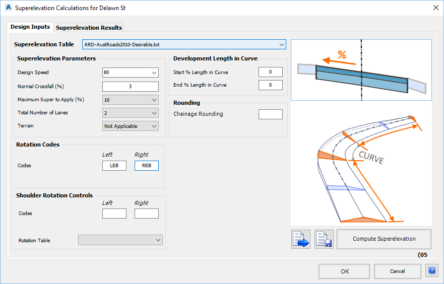
Upon selecting the command the user is prompted to select an alignment. After selecting an alignment, the following form is displayed:
Design Inputs Tab The Design Inputs tab defines the general design parameters to be used for creating the superelevation.
Superelevation Table: The Superelevation Table is used to determine the superelevation lengths and cross falls to apply to each Curve. Superelevation Parameters Design Speed Pick list available to select the design speed - speeds read from the Country specific superelevation table.
Note: This pick list can be over typed as required. In the case of USA speeds, it may be desired to manually set the required speed as the list may not update based on the Superelevation Table selected.Normal Crossfall(%) Sets the crossfall left and right of the centreline where no superelevation is applied. Maximum Super to Apply (%) Pick list to define the maximum superelevation (crossfall) to be applied to the Road. Total Number of Lanes Pick list defines the number of lanes for the Road (both directions) - options are 2, 4 or 6. Terrain Pick list of terrains available pending the local requirements. Rotation Codes Codes selected here will have crossfall/width adjusted as per the Superelevation Results. Codes - Left Controls which code left of centreline will be rotated initially using the Superelevation Parameters, and finally by the Superelevation Results. Default value is set by the Active Drawing Settings, Intersection Through Code input. Codes - Right Controls which code left of centreline will be rotated initially using the Superelevation Parameters, and finally by the Superelevation Results. Default value is set by the Active Drawing Settings, Intersection Through Code input. Shoulder Rotation Controls Codes - Left Controls which code left of centreline will be rotated. The Shoulder Rotation File controls the shoulder rotation. Codes - Right Controls which code left of centreline will be rotated. The Shoulder Rotation File controls the shoulder rotation. Rotation Table Select the required .shRot file. This file is a text file that is stored in the 'common' folder with the configuration files (click here for more information on where configuration files are stored). It can be edited by the designer to suit the requirements of a particular job. See Shoulder Rotation file details below. Development Length in Curve Start % Length in Curve Type in what percentage of the total superelevation development length is allowed to occur inside the curve on the approach. End % Length in Curve Type in what percentage of the total superelevation development length is allowed to occur inside the curve for the departure. Rounding Chainage (Station) Rounding Determine the rounding to apply to the calculated Superelevation Results. For example, typing a value of 0.1 will cause the Chainage (Station)s to round to one decimal place. Load Style The Design Inputs can be saved to file for re-use on any project. After clicking on this button type in a save name to save the file. Save Syle The Design Inputs can be saved to file for re-use on any project. After clicking on this button select a Saved Style to populate the Design Inputs. Compute Superelevation Used to apply the settings and create the superelevation. A warning message will be displayed after clicking on this button. Click on Yes to continue and apply the general design controls in the Design Input tab and open the Superelevation Results tab for editing the results.
All data in the Superelevation Results tab will be replaced by applying the design parameters in the Design Inputs.
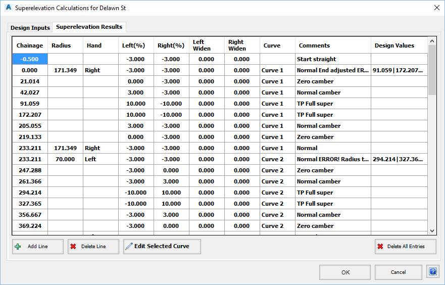
Superelevation Results The Superelevation Results tab is used to review and edit the Superelevation applied using the design parameters.
Table The table on this tab form details every aspect of the crossfall and road width adjustments that are to be applied to the Road. Outputs can be manually adjusted. Chainage (Station) Chainage (Station) at which the crossfalls and widths are applied. Radius Curve radius (read from the alignment). Hand Direction of the curve (left curve or right curve). Left % Crossfall of the Left Side Code (as set in Pavement Rotation Controls). Right % Crossfall of the Right Side Code (as set in Pavement Rotation Controls). Left Widen Incremental change to the width of the Left Side Code (as set in Pavement Rotation Controls). Right Widen Incremental change to the width of the Right Side Code (as set in Pavement Rotation Controls). Curve Curve number. Automatic input by the software. Incremented from 1, working from the start of the alignment to the end. Comments Text field. General information supplied regarding the superelevation. Design Values Information stored by the software. Information is separated by the delimiter | . The first two figures show the Curve start Chainage (Station) and the Curve end Chainage (Station).
The message 'Normal ERROR! Radius too small' tells the user that the radius was smaller than the smallest radius contained in the Superelevation Table (indicating a sub standard curve radius).Do not edit this data - it is used internally by the program to store information on the curve radii etc
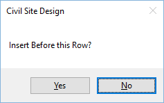
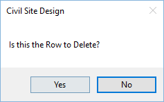
Add Line New lines can be added by clicking on a location in the table and then clicking on Insert Line. The new line will be inserted above the selected location. Users will be prompted to confirm row insertion: Delete Line Click this button to delete the currently highlighted line. Users will be prompted to confirm the delete: Edit Selected Curve Superelevation can be adjusted for any curve along the road by editing the design parameters for the curve. To do this:
- Click on a row that refers to the Curve to be edited
- Click on Edit Selected Curve
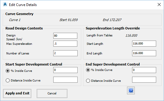
Curve Geometry Data confirms the curve number with the start and end Chainage (Station)s. Road Design Controls Establish the adjustments to the Road design aspects. Design Speed Type in the design speed for the Curve selected. Max Superelevation Type in the maximum crossfall. Units are m/m or ft/ft. Number of Lanes Type in the number of Lanes (2, 4, 6). Superelevation Length Override Designers can set a superelevation length for the curve. Start Length Adjust the superelevation length applied on approach to the Curve. End Length Adjust the superelevation length applied on departure from the Curve. Start Super Development Control Adjust the superelevation controls into the curve. % Inside Curve Toggle this on to make active. Set a % to extend the superelevation development inside the Curve on the approach. Distance Inside Curve Toggle this on to make active. Specify a distance in m to extend the superelevation development inside the Curve on the approach. End Super Development Control Adjust the superelevation controls on the departure from the curve. % Inside Curve Toggle this on to make active. Set a % to extend the superelevation development inside the Curve for the departure. Distance Inside Curve Toggle this on to make active. Specify a distance in m to extend the superelevation development inside the Curve for the departure. Apply and Exit Click to apply changes and exit. Cancel Click to exit without applying the changes. Delete All Entries Used to clear all entries in the table. OK Saves the current applied superelevation (as set in the Superelevation Results tab) and exits the form. Cancel Exits the form without saving changes made since opening the form.
Superelevation Tables - Output Control
Superelevation tables are used to determine the superelevation lengths and cross falls to apply to each Curve.
Preliminary design tables have been provided for the following Countries:
- Australia
- ARD-AustRoads-Speed.txt file - DO NOT DELETE THIS DEFAULT FILE
- ARD-AustRoads2010-Desirable.txt - desirable minimum superelevation lengths
- ARD-AustRoads2010-Absolute.txt - absolute minimum superelevation lengths
- India (Internal to the software - no file selection required)
- U.S.A. ARD-Imperial-Speed.txt - based on AASHTO settings
- South Africa ARD-SA-Superelevation.txt - based on metric AASHTO settings
Note: It remains the Designer's responsibility to review these tables to ensure that they meet the local, state and/or country standards.
Special Note: The superelevation files must be stored in the 'common' directory and have a name with prefix ARD (eg: ARD-Superefile.txt) and extension .txt to be included in the list of available superelevation files.
Superelevation applied to a Road (excepting India) is made based on a superelevation table:
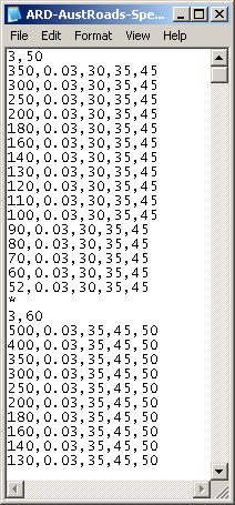
Shown, above, is part of the Superelevation Table created for Australian road design conditions (ref: Austroads Rural Road Design, 2003 - absolute minimum standards). The format of the table (comma delimited text file) is as follows:
- Requested Super (%), Speed
- This is followed by a series of lines setting out the superelevation to be applied depending on the radius of the curve:
- Radius, Maximum Superelevation to Apply, Superelevation Length (1 lane), Superelevation Length (2 lanes), Superelevation Length (3 lanes)
Each Superelvation/Speed combination is separated by a line containing an asterix (*).
Shoulder Rotation Files
The format of a Shoulder Rotation file is shown, below:
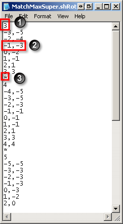
The shoulder rotation file is a text file that is saved in the 'common' folder, with the extension .ShRot. To learn more about where software configuration files are stored click here.It contains a number of sections which define the relationship between the pavement crossfall and the shoulder crossfall for a range of maximum crossfalls.
1. The first line in the section specifies the maximum crossfall being applied to the roadway.
2. Subsequent lines specify the actual road crossfall and the required crossfall for the shoulder code/s. Values of the shoulder crossfall are interpolated from this table. These 2 values MUST be separated by a comma (,).
It is assumed that the values in the table are increasing by the road crossfall and are in sequence.
3. An asterisk (*) indicates the end of a section.