Create/Edit Road
Icon: ![]()
![]()
Menu: Roads > Create/Edit Road
Ribbon: Roads Tab > Design Panel > Create/Edit Road
Introduction
An integral part of the software is the process of creating Road Strings (aka Roads). A Road is a special type of String object: as well as managing vertical and cross section geometry it also recognises other Roads where they intersect, with side road centrelines adjusting to match the cross section of main roads.
This command enables the creation of Road Strings which can then be designed vertically and managed with cross sections and interacts with other Road Strings where they intersect. If it is not desired for Roads to match levels where they intersect, a String (Profile) object should be created instead.
This command provides two distinct functions:
- Enables the creation of NEW Road Strings
- Opens the Vertical Grading Editor for existing CSD Objects (including Roads, kerb returns, cul-de-sacs, knuckles, roundabouts or other independent String/Profile) to be edited - selection can be made graphically or from a list.
Special Notes
It is vital that the following conditions are met for successful creation of a Road with this command:
- An existing surface must exist in the drawing AND extend for the full extent of all Road alignments and a sampling width for the proposed cross section, so that the software can assign 'existing' surface levels
- Alignments start/end at another continuous Road string alignment for a tee intersection - the intersection point must not meet the start/end of the 'main' road string alignment that it connects to, if automated intersections and kerb returns are expected.
- Alignments fully cross another Road string alignment, for crossing roads.
To optimise the Auto Road Creation command, the following is recommended:
- For Civil 3D customers, put r- in the description of the alignment.
- For non-Civil 3D customers, alignments must be created with the Type set to 'Road'
It is typically required at the first alignment is created as a Road String, even if intersection matching isn't required.
For more information on the requirements please review the Design information
Details
Upon starting the command the software will:
- Scan the software for other Road Strings already created.
- Check for intersections and prompt the user to select the side road where 'road' alignments cross - click here for more information regarding intersections at crossing alignments
- Allow the designer to select an alignment in the drawing (either by screen selection or from a form)
Upon selection of the alignment from the drawing or from a form, the software checks if it is an existing Road object:
- If a Road has not been created for the alignment, then the software will proceed through the Create Road form, below.
- If a Road Object (whether it be a Road, Kerb Return, Cul-de-sac, Profile, Knuckle or Roundabout) has been created from the alignment, then the software will open the
 Vertical Grading Editor for the designer to edit the vertical grading and/or the cross sections as required.
Selecting an Alignment for an Existing Road
When the command is started the command prompt will request the user to 'Select alignment, or press Enter to select from a list'.
Designers can either pick an alignment from the drawing or press [enter] to obtain a list of available alignments:
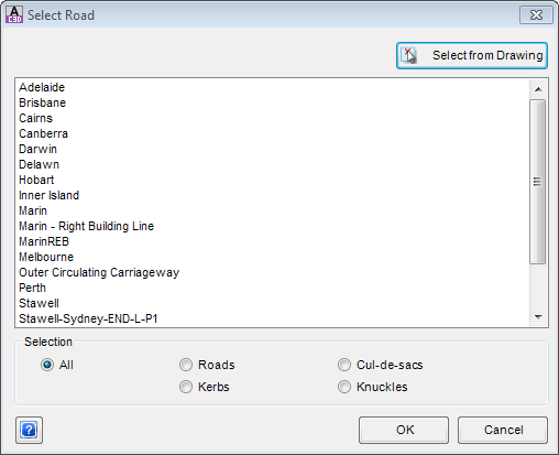
To select an alignment, pick one from the list and click OK. |
|
| List of Alignments | Displays all alignments in the drawing that may be used as Road, Cul-de-sac, Kerb or Knuckle Strings, as well as any other CSD Strings (roundabouts, general Strings, etc).
Use the left mouse button to select an alignment to either create as a Road or to open into the |
| Selection | This area allows the designer to filter the list for particular road objects |
| Selection Options: |
|
| Select from Drawing | Click on this button to enable graphical selection of an alignment in the drawing. |
| OK |
Proceed with either creating a new road or viewing the |
| Cancel | Exit the form without selecting an alignment |
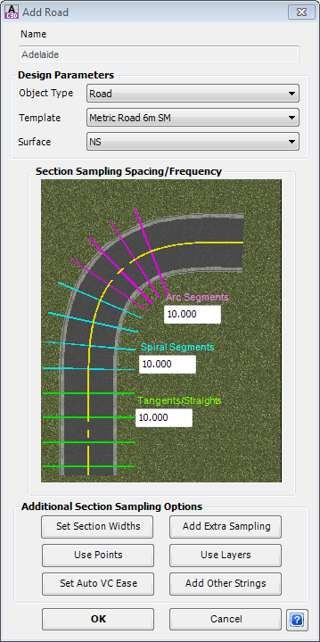
Creating a NEW Road
If an alignment is selected that has the prefix 'r-' in the description field of the alignment and it is NOT currently a Road in Civil Site Design then the designer will be guided through the process of creating a Road from the selected alignment.
Roads interact with each other, with Side Road profiles adjusting to match the cross section of the Main Roads at the intersections and the side road cross sections trimming to form up correct Surface and Corridor models.
The form enables the Designer to:
- Assign a typical cross section for the Road (through the assignment of a
 Template)
 - Assign the 'natural' surface levels for the Road
- Choose the sampling frequency along the Road
The details of the Create Road form is as follows:
 |
|||||||||||||||||||||||||||||||||||
| Alignment/Road Name | This will not be editable as the software uses the alignments name here. | ||||||||||||||||||||||||||||||||||
| Design Parameters | |||||||||||||||||||||||||||||||||||
| Road Type | LEAVE THIS SETTING AS 'Roads'. The pick list includes other road types, but is inactive at this time. | ||||||||||||||||||||||||||||||||||
| Select Template | Use the pick list to select an appropriate Template to apply to the Roads. For more information on creating custom templates see the |
||||||||||||||||||||||||||||||||||
| Select Sampling Surface | Use the pick list to select the Surface to project any batters to as well as the comparison surface to see cut/fill depths for the design vertical grading. | ||||||||||||||||||||||||||||||||||
| Section Sampling Spacing/Frequency | |||||||||||||||||||||||||||||||||||
| Arc Segments |
Distance between sample sections along arc segments of the alignment centreline. |
||||||||||||||||||||||||||||||||||
| Spiral Segments | Distance between sample sections along spiral segments of the alignment centreline. | ||||||||||||||||||||||||||||||||||
| Tangents/Straights | Distance between sample sections along tangent segments of the alignment centreline. | ||||||||||||||||||||||||||||||||||
| Special Notes:
All geometry points, including the start/end points of the alignment, will automatically be sampled. |
|||||||||||||||||||||||||||||||||||
| Additional Section Sampling Options | |||||||||||||||||||||||||||||||||||
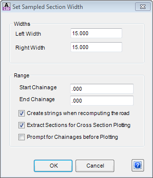
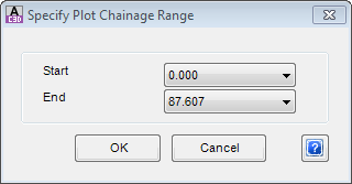
| Set Section Widths | This enables the designer to adjust the default cross section widths (initially populated from the Selecting this option displays the following form:
|
||||||||||||||||||||||||||||||||||
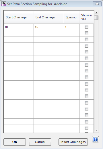
| Add Extra Sampling | Opens a form to enable the establishment of user selected chainages and different chainage sampling frequencies:
|
||||||||||||||||||||||||||||||||||
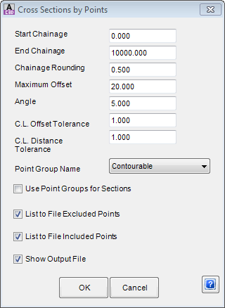
| Use Points | Opens a form to enable the establishment of cross sections directly from COGO points in the drawing. Users establish filtering controls for searching for points to use. Point locations can be used for setting sampling chainages.
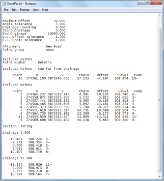
Cross Sections of the existing surface are built directly from the POINTS used - points are assumed to run along section lines at a 'common' chainage location for sampling of section elevations. Upon selecting the command the following form is displayed:
|
||||||||||||||||||||||||||||||||||
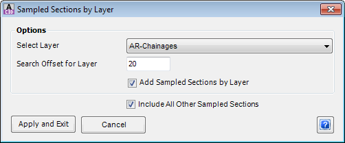
| Use Layers | Opens a form to enable the establishment of additional section sampling based on the ENDPOINTS of Lines and Arcs on a user selected layer in the drawing:
|
||||||||||||||||||||||||||||||||||
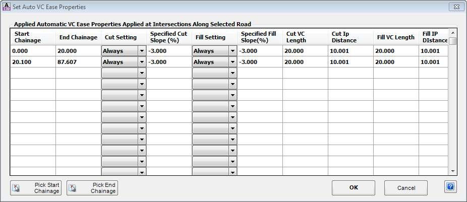
| Set Auto VC Ease | Opens a form to control how side road elevations match up and extend from the edge of a main road. These controls can be adjusted after creating a Road.
Form details are identical to the |
||||||||||||||||||||||||||||||||||
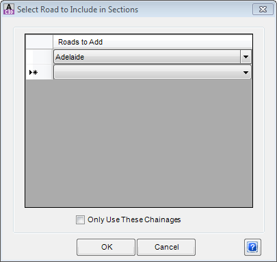
| Use Other Road | Opens a form to enable the adding of sampling from another Road/String. It is often desirable, when designing a string that is related to sections on another string/road, to sample the exact same sections.
|
||||||||||||||||||||||||||||||||||
| Create/Update | Click to create a Road from the alignment | ||||||||||||||||||||||||||||||||||
| Cancel | Click to cancel the command without creating a Road. | ||||||||||||||||||||||||||||||||||
Special Note: Users are not required to add extra sampling for the start/end, tangent/arc, arc/spiral, spiral/spiral or spiral/tangent geometry points along the alignment. The software automatically includes a sampled section at these points.
After the Road is created, yellow section lines will be displayed in the drawing to represent the sampling applied by Civil Site Design to each of the alignments.
| Notes: | The width of the yellow section lines is controlled via the Set Section Widths form. |
| The layer that these lines are created on is controlled in the Active Drawing Settings - Layer Names tab. The Type is known as 'Cross Section Lines' - the layer name set here are used to create the layers in the drawing. |
The ![]() Vertical Grading Editor will immediately open, with a default profile design provided and with the typical cross section applied.
Vertical Grading Editor will immediately open, with a default profile design provided and with the typical cross section applied.
Special Note: If any 'mistakes' were made at the time of creating the Road object, or if it is required to edit the sampled sections to update against a revised surface or reference a different surface users can run the ![]() Resample Road Cross Sections command.
Resample Road Cross Sections command.