Auto Model Datum
Icon: ![]()
![]()
Menu: Roads > Auto Model Datum
Ribbon: Roads Tab > Modelling Panel > Modelling Drop-down > Auto Model
Datum
Introduction
After using Civil Site Design to create the road network this command creates a single surface of the DATUM for the entire road network, including all trimming at the intersections, cul-de-sacs, knuckles and roundabouts.
The new surface is called DatumSurface and is stored as an CSD Surface (also known as an CSD Quick Surface in AutoCAD Civil 3D)
Note: The DatumSurface does not automatically update when design changes are made to any string that makes up the Road Network - designers need to click on the command again to update DatumSurface.
Any CSD Surface (including DatumSurface) can have it's display edited using the
![]() Create/Edit Surface
command.
Create/Edit Surface
command.
Layers used to display the surface object are managed by the
![]() Active Drawing Settings >
Layer Names Tab. The component layers used to display different
components of the surface (such as the major and minor contours) are managed via
the
Active Drawing Settings >
Layer Names Tab. The component layers used to display different
components of the surface (such as the major and minor contours) are managed via
the
![]() Create/Edit Surface
for CSD Surfaces and Civil 3D Styles for Civil 3D Surfaces.
Create/Edit Surface
for CSD Surfaces and Civil 3D Styles for Civil 3D Surfaces.
Civil 3D Users - Creating a Surface
A Civil 3D surface can be created for DatumSurface (and any other CSD
Surface) by using the
![]() Export CSD Surface
to Civil 3D command.
Export CSD Surface
to Civil 3D command.
Before Running Auto Model - Settings
The default output display for the Surface (whether an CSD Surface or a Civil 3D
Surface) is controlled from the
![]() Active Drawing Settings > Modelling Tab.
Active Drawing Settings > Modelling Tab.
Details
After running the command, the drawing will update to include a new surface. Surface Definition data will include breaklines.
Message reports will display to confirm the model output details, some of
which can be suppressed by adjusting settings in the
![]() Active Drawing Settings > Modelling Tab.
Active Drawing Settings > Modelling Tab.
Details
This command can be initiated at any time during the design process, however it is recommended that you have created all the roads before running the command to ensure that the intersection trimming works as expected. This command will generate a single surface model of the subgrade DATUM for the entire road network.
The ![]() Active Drawing Settings form controls the Surface Styles that will be used to display the object.
Active Drawing Settings form controls the Surface Styles that will be used to display the object.
The object layer for the surface, as well as the layer names for the breaklines are read from the
![]() Active Drawing Settings - Layer Names (DatumSurface for the surface object layer, 3D Poly Modelling, 3D Poly Kerb Infill, 3D Poly Extra VC for the breaklines).
Active Drawing Settings - Layer Names (DatumSurface for the surface object layer, 3D Poly Modelling, 3D Poly Kerb Infill, 3D Poly Extra VC for the breaklines).
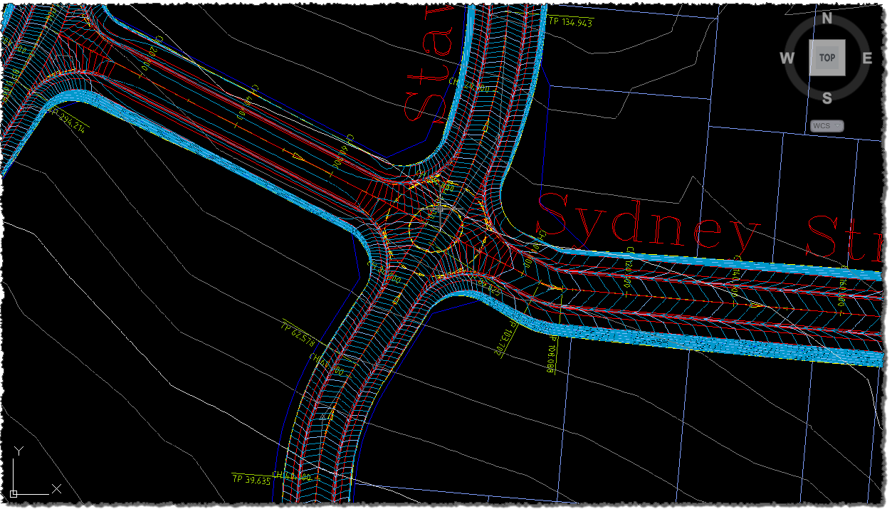
Before the command is run:
After the command is run:
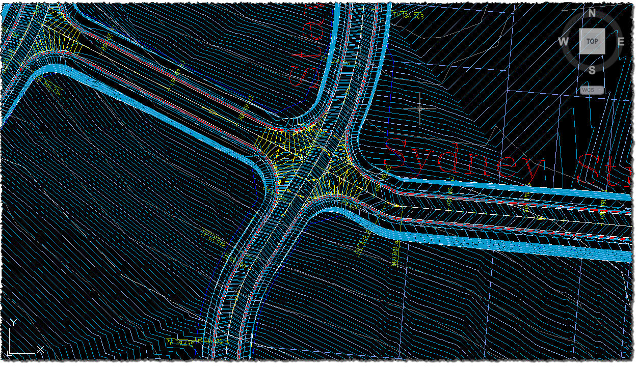
The datum for the applied subgrades are used to build the model.
Surface styles and layer controls are managed similarly to the
![]() Auto
Model command.
Auto
Model command.
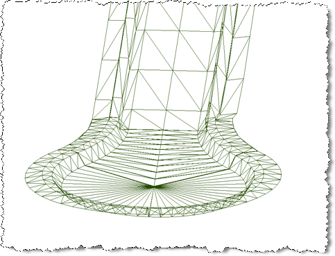
3D View of the Surface
Shown below is a surface model in 3D created using the Auto Model Datum command. The datum is clearly shown here, with a significant rise off the back of the kerb to the footpath, then through and down for the footpath.
|