Integral to all design processes is the need to create material reports to be used for cost estimates and design comparisons.
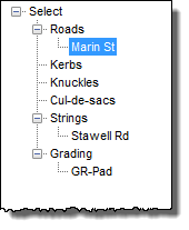
On starting the command the Designer is asked to nominate the required road by selecting it from the screen, or from a list.
| Sectional Data |
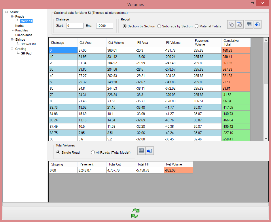
The user can choose how to report & output the data for volumes. This top frame heading also lists the String that is being reported and whether intersection trim controls have been applied to the volumes. |
| |
 |
| Start Chainage |
Enter a chainage to begin the volume report calculations. If left blank, then CSD will default to the first chainage. |
| End Chainage |
Enter a chainage to end the volume report calculations. If left blank, then CSD will default to the last chainage. |
| Settings & Output |
These functions enable the user to control the output of the Volume Reports Form & AutoCAD Tables |
| |
|
 |
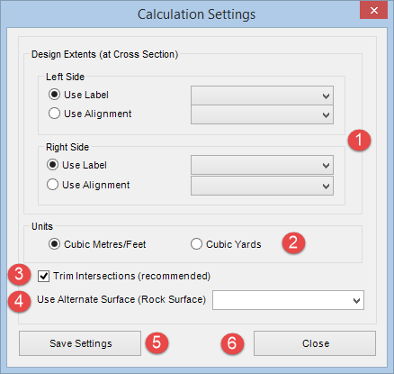
Calculation Settings |
| |
 |
 |
Left / Right Side |
Use Label |
Select this option and use the pick list to select a code for the Left / Right side. |
|
| Use Alignment |
Select this option and use the pick list to select an alignment for the Left / Right side. |
|
 |
Pick Cubic Metres / Feet or Cubic Yards |
 |
Trim Intersections. If ticked on, the volumes are adjusted as follows: |
| |
- Implications for intersections:
- Main Road strings are trimmed back to the LEB/REB codes, from kerb return string to kerb return string across the intersection zone (no volumes are calculated outside of these codes along the main road)
- Side Road strings are trimmed back to the centreline, from kerb return string to the intersection left and right side (no volumes calculated at all)
- Kerb return strings that have a RDUM code (or LDUM code for users opting to drive on the right hand side of the road) will note that the RDUM/LDUM code extends out to the LEB/REB code of the main road and to the CL of the side road, for the full extents of the kerb return.
- Implications for cul-de-sacs
- Main Road strings are trimmed back to the centreline (CL code) on the left from where the left side cul-de-sac alignment starts/ends and on the right side from where the right side cul-de-sac alignment ends/starts
- Cul-de-sac strings that have a RDUM code (or LDUM code for user option to drive on the right hand side of the road) will note tha tthe RDUM/LDUM code extents out to the CL of the Main Road string.
|
 |
Allows assigning an alternative surface for volumes. It is assumed that this surface extends for the ENTIRE string extents and covers the full width of ALL sections along the string. Unexpected results will occur if this is not the case.
If specified, volumes are calculated between this surface and the bottom of the pavement layers of the design. |
 |
Select to save current changes |
 |
Close to Exit to the Volume Reports |
|
 |
Report Settings |
| |
|
| |
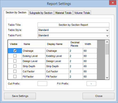
This form is used to choose what items are displayed in the Volume Reports form & control the AutoCAD Table Style report output. The user can customise each Report Type depending on requirements.
Each tab can be controlled as follows: |
| |
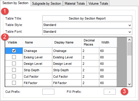
Section by Section |
| |
 |
|
Table Title: Double click the cell to name the AutoCAD table to be outputted to screen |
| Table Style: Select an existing AutoCAD table style from the list |
| Table Font: Select a font from the list |
|
Controls what items are displayed in the Volume Reports Form & AutoCAD table: |
| Visible |
Name |
Display Name |
Decimal Places |
Width |
| Tick to make item Visible |
Predefined reporting item |
Double click to edit |
Double click to edit
(Default value = 2) |
Double click to edit
(Default value = 60) |
|
| Cut Prefix |
User can type a prefix value to indicate 'cut' on the Report Form ie. |
| |
|
| Fill Prefix |
User can type a prefix value to indicate 'Fill' on the Report Form |
|
|
| |
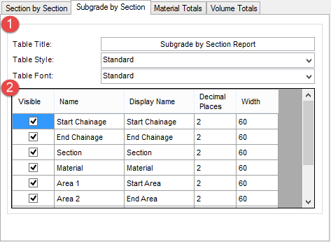
Subgrade by Section |
| |
 |
|
Table Title: Double click the cell to name the AutoCAD table to be outputted to screen |
| Table Style: Select an existing AutoCAD table style from the list |
| Table Font: Select a font from the list |
|
Controls what items are displayed in the Volume Reports Form & AutoCAD table: |
| Visible |
Name |
Display Name |
Decimal Places |
Width |
| Tick to make item Visible |
Predefined reporting item |
Double click to edit |
Double click to edit
(Default value = 2) |
Double click to edit
(Default value = 60) |
|
| |
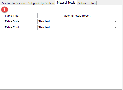
Material Totals |
| |
 |
|
Table Title: User can name the AutoCAD table to be outputted to screen |
| Table Style: Select an existing AutoCAD table style from the list |
| |
Table Font: Select a font from the list |
| |
|
| |
|
|
| |
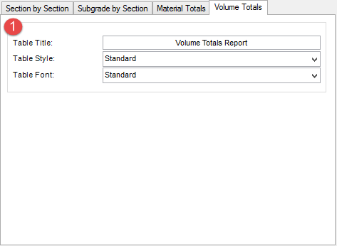
Volume Totals |
| |
 |
|
Table Title: User can name the AutoCAD table to be outputted to screen |
| Table Style: Select an existing AutoCAD table style from the list |
| |
Table Font: Select a font from the list |
| |
| |
|
|
 |
AutoCAD Table |
| |
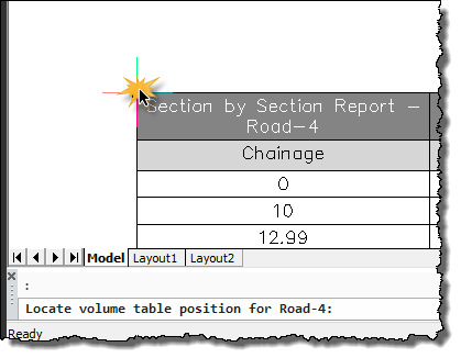
This command will output an AutoCAD table into the drawing.
If a table has already been created for the current Alignment & Report Type, the existing table will automatically be updated when selecting this option.
If there is no table in the drawing for the current Alignment & Report Type, the user will be prompted on screen. |
| |
| The user will be prompted on screen to position the top left corner of the table and left click to finish and return the form: |
 |
|
 |
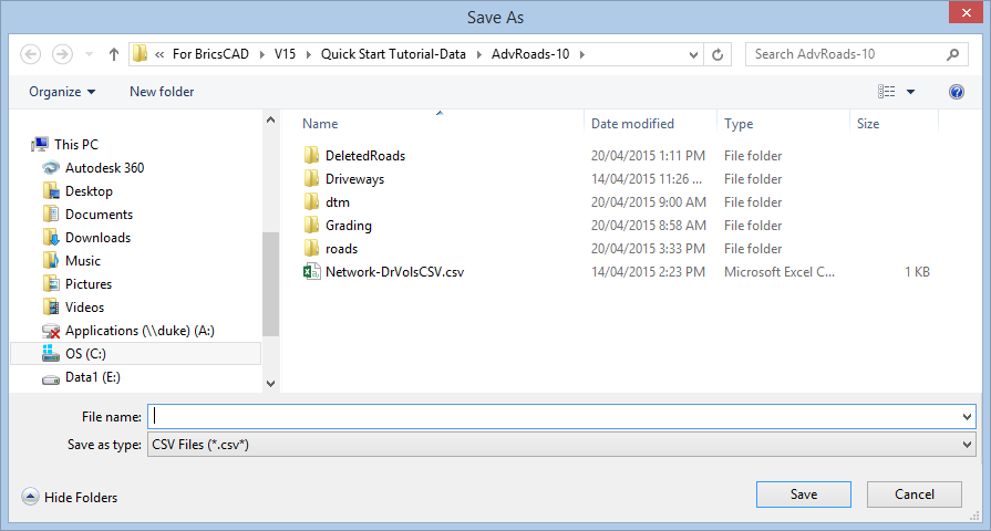
Output Table to CSV |
| |
| On selecting this option, the user will be prompted on screen to save the CSV file. |
 |
|
| Report Type |
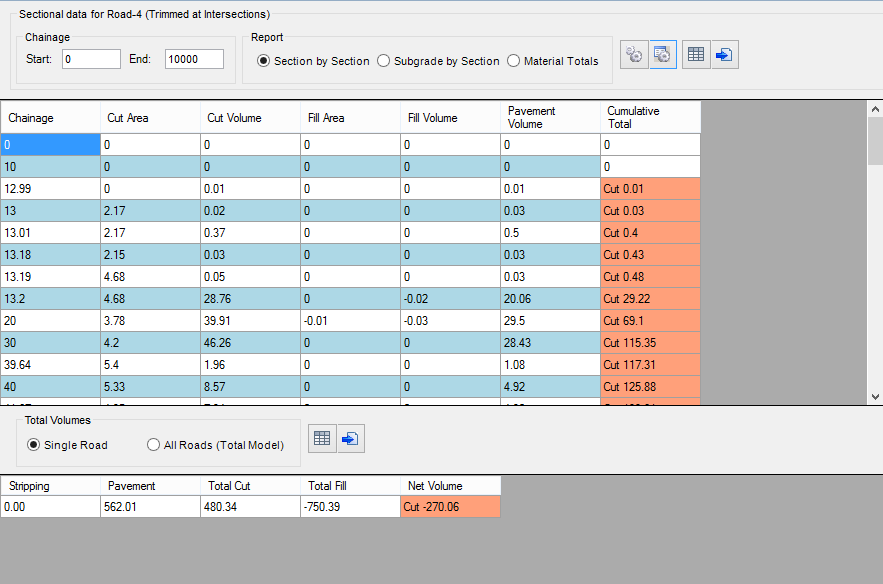
The user can choose from three different types of volume calculation output |
| |
Section by Section |
| |
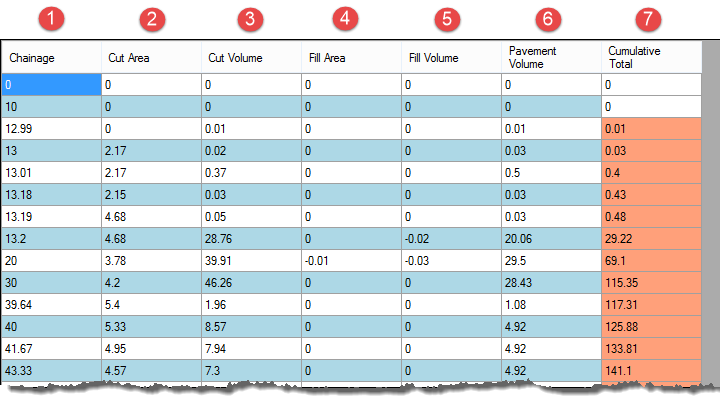
In this report the user can output cumulative volumes base on the current Sampled Sections. Note: Default reporting columns shown - additional reporting columns can be added using the Report Settings. |
| |
 |
|
Chainage at which the volume calculation is taken.
Additional chainages can be added using the Add Extra Sections
command. |
| |
Cut area between chainages (sq.m) |
| |
Cut Volume between chainages (cu.m) |
| |
Fill Area between chainages (sq.m) |
| |
Fill Volume between chainages (cu.m) |
| |
Pavement Volume (cu.m) |
 |
Cumulative Total (Total Area cu.m between start chainage and current) |
|
| |
Ouput |
| |
 |
|
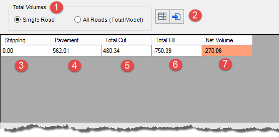
The user can choose to report the single Road or All Roads (based on the Totalmodel) |
|
|
User can choose to output the Total Volume data to an AutoCAD table |
|
|
|
User can choose to output the Total Volume data to a CSV file |
|
|
|
Stripping |
The stripping volume is calculated by applying a depth of material removal between the left and right extents of the design cross sections (normally batter to batter). The strip is value determined from Stripping in the Design Data Form |
|
|
Pavement |
Total Volume of Pavement Material |
|
|
Total Cut |
Total Cut material |
|
|
Total Fill |
Total Fill material |
|
|
Net Volume |
Net Volume calculation |
|
|
| |
Subgrade by Section |
| |
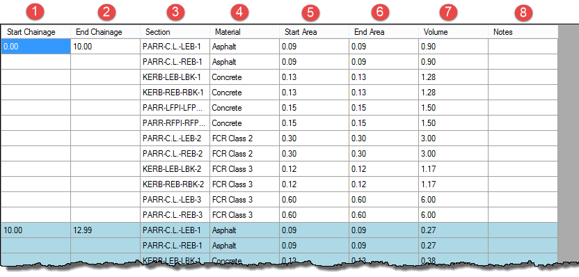
In this report the user can output volumes between design codes. Note: Default reporting columns shown - additional reporting columns can be added using the Report Settings. |
|
|
|
Start Chainage at which the volume calculation is taken.
Additional chainages can be added using the Add Extra Sections
command. |
| |
End Chainage at which the volume calculation is taken.
Additional chainages can be added using the Add Extra Sections
command. |
| |
The Section on the road |
| |
The codes between which the volume calculation is taken. Both left & right sides are calculated seperately. |
| |
The area of material at the start Chainage |
| |
The area of material at the end Chainage |
| |
Total Volume of material in that section |
 |
Notes can be added to this column. Double click the cell to add notes. |
| |
Output |
| |
|
|
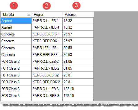
Material |
Displays the material between the design code between whiich the volume calculation is made |
|
Region |
Displays the design codes between which the volume calculation is made |
|
Volume |
Total Volume of material wiithin the region |
|
| |
Material Totals |
| |
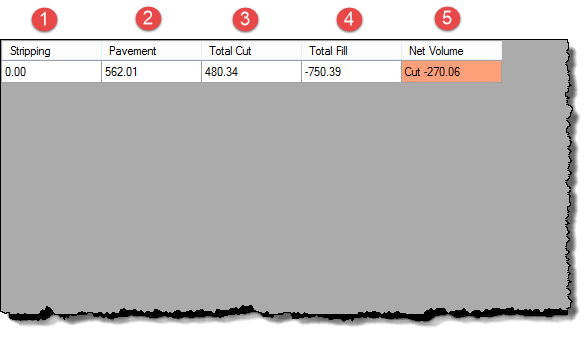
In this report the user can output Total Volumes for an alignment |
| |
 |
|
Stripping |
The stripping volume is calculated by applying a depth of material removal between the left and right extents of the design cross sections (normally batter to batter). The strip is value determined from Stripping in the Design Data Form |
| |
Pavement |
Total Volume of Pavement Material |
| |
Total Cut |
Total Cut material |
| |
Total Fill |
Total Fill material |
| |
Net Volume |
Net Volume calculation |
|
| |
Output |
| |
 |
|
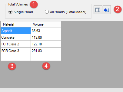
The user can choose to report the single Road or All Roads (based on the Totalmodel) |
|
|
User can choose to output the Total Volume data to an AutoCAD table |
|
|
|
User can choose to output the Total Volume data to a CSV file |
|
|
|
Material |
Displays the Pavement Material |
|
|
Pavement |
Total Volume of Pavement Material |
|
|
| |
|
| Refresh |
Refreshing the Reports |
| |

|
| |
If changes are made to a surface, alignment or profile, this button will enable the user to globally refresh the Volume Report Form & AutoCAD tables on screen and update the contents. |