Setout
Icon: ![]()
![]()
Menu: Roads > Setout
Ribbon: Roads Tab > Plan Production Panel > Multi-Setout Dropdown >
Setout
Introduction
Civil Site Design has a very wide range of options for creating setout data for its designs.
Designers and draftspersons may prefer creating Civil 3D Points and Civil 3D Tables for the setout. Click on the link below to review a white paper on this:
| Click on the icon (left) to review a white paper regarding Civil 3D setout of data. |
Details
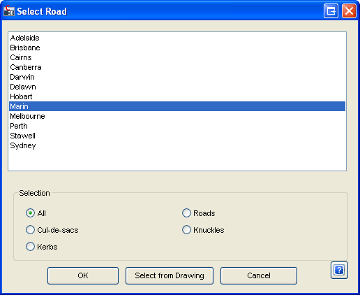
On starting the Setout command the Designer is requested to select the Alignment (Road Object) in the drawing or press [Enter] to select from a list box, as shown below.
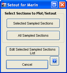
After selecting the Alignment, a form is then displayed to allow the selection of sections to be shown in the profile plot.
 |
|
| Selected Sampled Sections | Use the Selected Sections list previously set up |
| All Sampled Sections | Use all the extracted data |
| Edit Selected Sampled Sections List | Select this to run the Select Sections to Plot command and edit the list of chainages to use |
| Cancel | Exit the command |
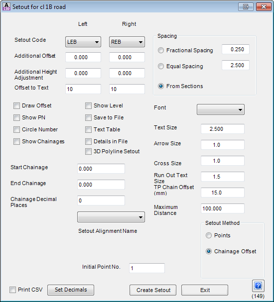
After selecting either Selected Sections or All Sampled Data, the setout form is displayed. The setout option provides a large number of options, so that the setout can be tailored as required.
 |
|||||||||||||||
| General Controls | |||||||||||||||
| Setout Code | Select the cross section labels (left and right of the C.L) from the list. Information can be generated for left and right if required. A blank entry means that item is ignored. | ||||||||||||||
| Additional Offset | Enter an amount to vary the offset of the set out point. | ||||||||||||||
| Additional Height Adjustment | Enter a height adjustment for the set out point | ||||||||||||||
| Offset to Text | Enter a distance in mm/in for the positioning of the text from the actual point (5 mm is typical). | ||||||||||||||
| Spacing |
Options include:
Note that for fractional and equal spacing, interpolation is used to obtain levels at the computed chainages. |
||||||||||||||
| Initial Point No. | Type in to set an initial setout point number for the current Road. The software may prevent overlapping setout numbers and automatically renumber points in conflict. | ||||||||||||||
| Output Options | |||||||||||||||
| Draw Offset | Toggle on to draw a line from the point to the text. | ||||||||||||||
| Show PN | Toggle on to draw the point number on the drawing. | ||||||||||||||
| Circle Number | Toggle on if the point number is enclosed in a circle. | ||||||||||||||
| Show Chainages | Toggle on to show the chainage on the drawing - note that if this option is selected the Circle Number option is disabled. | ||||||||||||||
| Show Level | Toggle on to show the level in the drawing | ||||||||||||||
| Save to File | Toggle on to create a file of information (required to create a text table). | ||||||||||||||
| Text Table | Toggle on if a text table is needed in the drawing. The table is drawn as a single Mtext object. After completion of the command select it and drag it to a suitable location in the drawing. | ||||||||||||||
| Details in File | Toggle on to write code and chainage data to the output file. | ||||||||||||||
| 3D Polyline Setout | Toggle on to select a 3d polyline in place of the road. If the 3D polyline option is selected, then a 3D polyline may be selected in place of the current road. | ||||||||||||||
| Start Chainage | Enter a value to start setout from. | ||||||||||||||
| End Chainage | Enter a value to end setout. | ||||||||||||||
| Chainage Decimal Places | Number of decimals for chainage. | ||||||||||||||
| Setout Alignment Name pick box | Displays if Setout Method is set to Chainage Offset. | ||||||||||||||
| Text Display Controls | |||||||||||||||
| Font | Select required text style - additional text styles are generated via the Fonts.txt file located in the Common folder. | ||||||||||||||
| Text Size | Enter text size required | ||||||||||||||
| Arrow Size | Arrow size at end of leader (in mm/in). | ||||||||||||||
| Cross Size | Cross size for the point (in mm/in). | ||||||||||||||
| Run Out Text Size | Text size for the remaining portion of a cul-de-sac. | ||||||||||||||
| TP Chain Offset (mm) | Text size for TP details in a kerb return. | ||||||||||||||
| Maximum Distance | Used for radial setout to specify the maximum distance from a point. | ||||||||||||||
| Setout Method | There are two Setout Methods (listed below) and each have specific controls | ||||||||||||||
| Points | Generates xyz listing of data | ||||||||||||||
| Chainage and Offset |
Generates chainages and offsets from the alignment name
specified A drop down list called Setout Alignment Name will appear. Pick from the list the alignment to use for chainage and offset reporting. |
||||||||||||||
| Initial Point Number | Set the initial point number for setout. If the point has already been used by the software, the next available point number will be used to start | ||||||||||||||
| Print CSV | Toggle this ON before output of the Setout to modify the format of the file created when Setout to File is toggled ON. The format will include commas between each setout field, enabling immediate opening and review in Microsoft Excel. The edited file can then be used to import Civil 3D points into the drawing for the setout. Click on the .pdf icon at the top of this form for more information regarding Civil 3D point setout from CSD. | ||||||||||||||
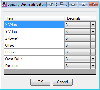
| Set Decimals |
Opens the following form for decimal control on outputs:
|
||||||||||||||
| Create Setout | Click to generate setout information in the drawing (and generate any setout reports, if selected) | ||||||||||||||
| Exit | Click to exit the form | ||||||||||||||
The options in the form provide to both plot data in the drawing and to write data to a file. Designers are recommended to try the various plotting options to see which ones most suit their requirements.