This is an interactive and interconnected vertical grading (profile) design environment with the following features and benefits:
The display of the 'tracker' that shows the relative location of the marker in the drawing is managed via a block in the Advanced Road Design Settings (ARD Settings) folder. Users are able to replace this drawing block as desired. The ARD Settings folder can be opened in Windows Explorer via the Open Settings Folder command in the General menu/ribbon. The block is named VGEMarker.dwg.
|
Details of the form are as follows:
|
 |
 Display Set Parameters form Display Set Parameters form |
The display of profile grades, high/low points, level information and text size can be controlled by the designer. This is achieved by clicking on the Display Set Parameters button.
Note: These controls are mirrored in the  Active Drawing Settings - Vertical Grading tab. Active Drawing Settings - Vertical Grading tab.
The controls of the form are graphically outlined below:

| Design Aids |
These settings assist the designer in achieving design compliance |
| Crest K Value |
Type in the required K value for creating crest curves. At the time of Adding IP's in the Vertical Grading Editor the software will use the specified K factor to indicate a suitable vertical curve length to achieve the K factor required for crest curves. |
| Sag K Value |
Type in the required K value for creating sag curves. At the time of Adding IP's in the Vertical Grading Editor the software will use the specified K factor to indicate a suitable vertical curve length to achieve the K factor required for sag curves. |
| Maximum Grade for Warning (%) |
Type in a desirable maximum grade (%). If the incoming or outgoing grade from a IP exceeds the maximum the grade indicator will turn Red. Otherwise the grade indicator is Green. |
| Minimum Grade for Warning (%) |
Type in a desirable minimum grade (%). If the incoming or outgoing grade from a IP is less than the minimum the grade indicator will turn Red. Otherwise the grade indicator is Green. |
| Items to Display |
Set what textual and other graphical information is displayed in the Vertical Grading Editor Design Window. Some of the relationships are shown, above |
| Show Chainages |
Tick on to show the Chainage values in the Vertical Grading Editor window. This will show the alignment chainages by default - if another road has been used for chainages (Use Other Road Chainages command), the other road chainages will display here. |
| Show Design Levels |
Tick on to show the Design Levels (Elevations) of the long section in the Vertical Grading Editor window |
| Show Level Differences |
Tick on to show the Level Difference between the Design Level of the vertical grading and the Sampled Surface in the Vertical Grading Editor window |
| Show Existing Levels |
Tick on to show the Existing (Sampled) Surface Levels in the Vertical Grading Editor window |
| Show High/Low Pt's |
Tick on to highlight the location of the high/low points in the Vertical Grading Editor window (small circle located along the design grading) |
| Show Grades |
Tick on to textually display the grades either side of the IP's and the Vertical Curve Lengths in the Vertical Grading Editor window |
| Show Volumes |
Tick on to display a summary of the bulk earthworks whilst editing using the  Raise/Lower IP by Fixed Amount command Raise/Lower IP by Fixed Amount command |
| Show Envelopes |
Tick on to graphically display Design Constraints (created via the Design Data Form) as additional long sections (profiles) in the design window. These are very helpful design aids to ensure grade and level controls to other features are met. Any Design Constraints (Envelopes) and also be used for assigning levels (elevations) when creating IP's. |
| Show Align. Chainages |
Tick on to display the chainages of the current alignment (this feature is only enabled subject to settings established via the Use Other Road Chainages command).
It is often useful to evaluate the levels of the current String in relation to another Road alignment. |
| Show Text XSect |
Not used. |
| Use Resheet For Level Diff. |
Tick on to display the difference between the Design Levels and applied Resheet Levels.
Note: This feature is only applied after a Resheet has been applied to the Road - see below for more information on applying a resheet to the design. |
| Show Pipes |
Tick on to display Pipes designed using Advanced Road Design on the Vertical Grading Editor window. Perpendicular pipes will be shown as a crossing pipe - all other pipes are shown superimposed in full. |
| Pipe Band Width |
Type in a value to set the search offset (relative to the current String being graded) to locate and display Pipes |
| Text Height (pixels) for Grades |
Change the pixel size for grade text shown at the top of the Vertical Grading Editor (if displayed). Minimum is 8 pixels. |
| Text Height (pixels) for Chainages and Levels |
Change the pixel size for grade text shown along the bottom of the Vertical Grading Editor (vertical text, if displayed). Minimum is 8 pixels. |
| % of Display Reserved for Text |
This is the percentage of space 'reserved' for text display at the bottom of the form - the vertical grading minimum level will extend down to this display percentage. |
| Apply and Exit |
Apply and exit. |
| Cancel |
Exit the form without adjusting the display. |
|
|
 VGE Customise Display VGE Customise Display |
This command allows the designer to customise the display of the Vertical Grading Editor (VGE). Here, the designer can edit the size of text displayed and assign colours to text and other items, such as the VGE background colour.
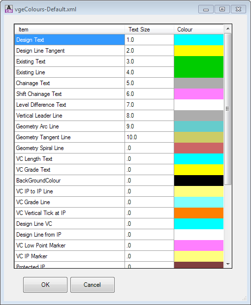
The Set Vertical Grading Editor Window Colours command has further information on this form.
|
| |
IP Create/Delete Tools |
This collection of commands enable creation and deletion of IPs |
|
 Insert IP Insert IP |
Adds an IP (PVI) to the Design Vertical Grading (Long Section/Profile).
Upon starting the command the Vertical Grading Editor prompt will display Click to Insert New IP. Use the mouse pointer to graphically select a location in the Vertical Grading Design Window. The following form is displayed:
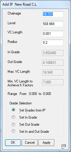 |
| Chainage |
Type in the chainage where the IP is required (the chainage is adopted from the Civil 3D Alignment Stations). Note: editable subject to the Grade Selection being applied |
| Level |
Type in the level (elevation) required (editable subject to the Grade Selection being applied) |
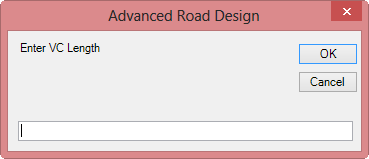
| VC Length |
Type in the length of vertical curve required |
| Radius |
Type in a Radius as an alternative to the VC Length |
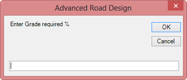
| In Grade |
Type in the grade required on the incoming tangent to the IP (editable subject to the Grade Selection being applied) - measured as % grade |
| Out Grade |
Type in the grade required on the outgoing tangent from the IP (editable subject to the Grade Selection being applied) - measured as % grade |
| Max. VC Length |
This is a reporting field identifying the maximum vertical curve that could be applied to the IP (based on the selected chainage) without overlapping another Vertical Curve or IP |
| Min. VC Length to Achieve K Factors |
This is a reporting field identifying the minimum Vertical Curve length that should be applied to achieve minimum K factors.
Note: The K factors are controlled from the Display Set Parameters form.
|
| Range From |
Displays the Chainage range between two IP's within which an IP could be located without overlapping any Vertical Curve/s |
| Grade Selection |
Designers can establish the chainage and level of the IP by specifying grade controls into and/or out of the IP. Inputs will be adjusted to suit the grade method specified |
| Set Grades from IP Level |
Default method. IP is defined by the Chainage and Level assigned. The In Grade and Out Grade parameters are disabled. |
| Set In Grade |
The IP level is defined by the incoming grade. The In Grade is enabled. The Level parameter is distabled. |
| Set Out Grade |
The IP level is defined by the outgoing grade. The Out Grade is enabled. The Level parameter is distabled. |
| Set In and Out Grade |
The IP level and chainage is defined by specifying both an incoming and outgoing grade for the IP. The In Grade and Out Grade parameters are enabled. The Chainage and Level parameters are disabled. |
| OK |
Create/Edit the IP and exit the form. |
| Cancel |
Exit the form without creating/editing the IP. |
| Apply |
Create/Edit the IP without exiting the form. |
|
|
 Delete IP Delete IP |
Deletes an IP (PVI) from the Design Vertical Grading (Long Section/Profile).
Upon starting the command the Vertical Grading Editor prompt will display Click on IP to Delete. Use the mouse pointer to graphically select an IP in the Vertical Grading Design Window. The selected IP will be deleted from the design. A new tangent will be created between the two adjoining IP's to form a continuous long section.
|
|
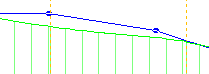
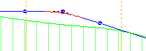
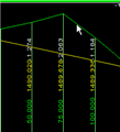
 Snap IP to 'Snap to' Constraint at Cross Section Snap IP to 'Snap to' Constraint at Cross Section |
Creates an IP at a cross section nearest the selected location, with the level (elevation) being adopted from the surface or Design Constraint as shown in the Snap To field (by default, this is the sampled (existing) surface).
Upon starting the command the Vertical Grading Editor prompt will display Select Point on <Snap To>. Use the mouse pointer to locate the nearest cross section where the IP is required. An IP will be created with levels applied based on the surface/constraint shown in the Snap To field, with a VC length of .001m.
Example shown, below:
Command Started - Select Location
 |
|
Command Complete - New IP at Chainage
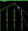 |
|
|
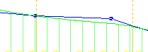
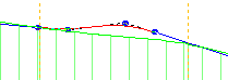
 Snap IP to 'Snap To' Constraint Snap IP to 'Snap To' Constraint |
Creates an IP with the chainage adopted from the location selected by the user and with the level (elevation) being adopted from the surface or Design Constraint as shown in the Snap To field (by default, this is the sampled (existing) surface).
Upon starting the command the Vertical Grading Editor prompt will display Select Chainage on <Snap To>. Use the mouse pointer to locate the chainage where the IP is required. An IP will be created with levels applied based on the surface/constraint shown in the Snap To field, with a VC length of .001m.
Example shown, below:
Command Started - Select Location
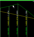 |
|
Command Complete - New IP at Select Location
 |
|
| |
IP Editing Tools |
This collection of commands provide graphical and numerical editing of the IP's |
|
 Edit IP Edit IP |
Numerically edit an IP by selecting it in the drawing.
Upon starting the command the Vertical Grading Editor prompt will display Select IP to Edit. Use the mouse pointer to graphically select an IP in the Vertical Grading Design Window.
Note: Except for the title of the form, the design inputs exactly match the Create IP command. Please refer above for more details on these inputs
|
|
 Specify Level Specify Level |
Edit an IP by setting a Chainage and Level that the design vertical grading must intersect. The selected IP will be raised/lowered so that the design vertical grading passes through the specified chainage and level.
Upon starting the command the Vertical Grading Editor prompt will display Select Required IP. After selecting the IP to edit the following form is displayed:
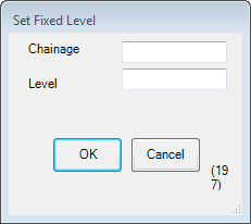 |
| Chainage |
Type in the required chainage |
| Level |
Type in the level (elevation) required |
| OK |
Exit the form and edit the IP level (elevation) so that the design vertical grading passes through the specified chainage and level |
| Cancel |
Exit the form without editing the IP |
|
|
 Move IP Anywhere Move IP Anywhere
|
Graphically move an IP anywhere within the limits of the constraining vertical curves or other IPs.
Upon starting the command the Vertical Grading Editor prompt will display Click on IP to Move. Click on or near an IP to select it for relocation. After selecting an IP it can be moved using the mouse. Click to store the new IP location.
|
|
 Slide IP on Grade Slide IP on Grade |
Graphically slide an IP along an incoming or outgoing grade.
Upon starting the command the Vertical Grading Editor prompt will display Click on IP to Slide. Click immediately to the left of an IP to hold the grade left of the IP. Click immediately to the right of an IP to hold the grade right of the IP. Use the mouse to set the new position of the IP. Click to store the new IP location.
|
|
 Move IP Up/Down by Mouse Move IP Up/Down by Mouse |
Graphically move an IP up or down whilst constraining movement along the chainage.
Upon starting the command the Vertical Grading Editor prompt will display Click on IP to Move. Click on or near an IP to select it for relocation. After selecting an IP it can be moved using the mouse. Click to store the new IP location.
|
|
 Move IP Left/Right Move IP Left/Right |
Graphically move a selected IP left/right and constrain any vertical movement.
Upon starting the command the Vertical Grading Editor prompt will display Click on IP to Move Left/Right. Click on or near an IP to select it and use the mouse to drag the IP left or right to set the new position of the IP. Click to store the new IP location.
|
|
Raise/Lower IP by Fixed Amount |
Move an IP up and down by a user defined increment.
Upon starting the command the Vertical Grading Editor prompt will display Select IP to Raise/Lower. After selecting the IP the prompt changes to Use Up/Down. Select Drawing to End and a scroll icon  appears. The IP level is then changed by the value shown in the text box each time the scroll Icon is selected. appears. The IP level is then changed by the value shown in the text box each time the scroll Icon is selected.
As indicated by the prompt, stop the command by clicking the left mouse button in the graphics area.
Special Note: If the option 'Show Volumes' is toggled on in the Display Set Parameters form, then a Volume Summary window will display showing the total earthworks and volumes. This information will update on movement of the selected IP up or down incrementally.
|
|
 Raise/Lower All IP's to achieve Balanced Earthworks Raise/Lower All IP's to achieve Balanced Earthworks |
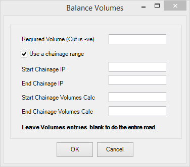 |
| Enter required volume |
Type in the required volume (cut requires '-') |
| Use Chainage Range |
Pick to define a chainage range to balance volumes |
| Start Chainage IP |
Input start chainage from which IP's can be modified when the calculation is undertaken |
| End Chainage IP |
Input end chainage to which IP's can be modified when the calculation is undertaken |
| Start Chainage Volumes Calc |
Input the start chainage from which the volume calculation will start |
| End Chainage Volumes Calc |
Input the end chainage to which the volume calculation will end |
| OK |
Exit the form and raise/lower IP's to achieve the set volume |
| Cancel |
Exit the form without editing the IP's |
|
|
 Add to all IP Levels Add to all IP Levels |
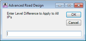 |
| Enter elevation change |
Type in the amount to raise/lower all IP's by |
| OK |
Exit the form and raise/lower all IP's by the change value |
| Cancel |
Exit the form without editing the IP's |
|
|
 Fit Vertical Curve/s Between IP's Fit Vertical Curve/s Between IP's |
This command is used to insert a either a single vertical curve or a vertical curve pair based on the incoming grade to the first IP and the outgoing grade from the second IP. The process is the same as is used for designing Kerb Returns and is as follows:
|
|
 Compute VC from Existing Data Compute VC from Existing Data |
This command provides access to a variety of methods to generate a vertical grading for the current ARD Object open in the Vertical Grading Editor.
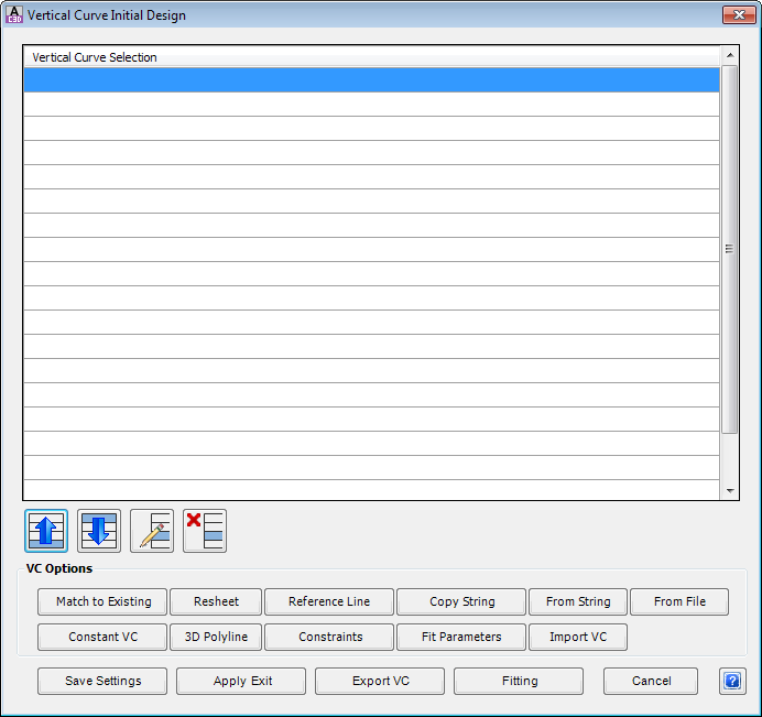
As VC Methods are applied they are added to the list. The Vertical Grading controls are applied in order, from the top to bottom of the list.
|
| VC Methods |
Command buttons enable the user to select the method desired for setting the vertical grading |
| Match to Existing |
This method allows the designer to create IP's at sampled sections (over a specified chainage range) and match the elevations of these IP's to a specified surface model. If the Use Fitting option is checked, the software will filter out the calculated IP's and smooth the design by inserting vertical curves. This option can also be used to add a level adjustment. For example, the designer might opt to match all levels to an existing surface and then raise this design by 50mm.
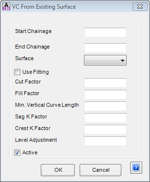
|
| Start Chainage |
Apply from start chainage |
| End Chainage |
Apply to end chainage |
| Surface |
Pick list for surface to extract levels from |
| Use Fitting |
Toggle this on to 'smooth' out the design |
| Cut Factor |
Allows for this amount of cut against the sampled surface before inserting a new IP |
| Fill Factor |
Allows for this amount of fill against the sampled surface before inserting a new IP |
| Min. Vertical Curve Length |
Sets the minimum desired vertical curve length |
| Sag K Factor |
Vertical curve lengths will be set from this K factor in sag situations, where possible |
| Crest K Factor |
Vertical curve lengths will be set from this K factor in crest situations, where possible |
| Level Adjustment |
Lifts/lowers the outputted fitted vertical grading |
| OK |
Apply and exit. |
| Cancel |
Exit the form without changing any data. |
|
| Constant VC |
Click on this option to create IP's at each sampled section and assign them all the same level. Form displays as follows:
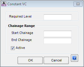
User input is as follows:
|
| Required Level |
Type in the desired level |
| Start Chainage |
Apply from start chainage |
| End Chainage |
Apply to end chainage |
| OK |
Apply and exit. |
| Cancel |
Exit the form without changing any data. |
|
| Resheet |
Click on this option to set the road centreline levels to acheive a minimum overlay depth for resheeting. Form displays as follows:
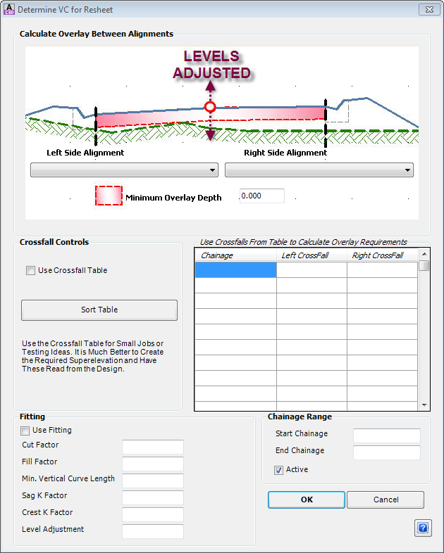
User input is as follows:
|
| Left Side Alignment |
Select left side alignment |
| Right Side Alignment |
Select right side alignment |
| Minimum Overlay Depth |
Sets the minimum thickness for overlay |
| Use Crossfall Tables |
If ticked command will use the crossfall tables rather than the alignments |
| Crossfall Table |
input values for chainage and crossfall to be used to calculate the overlay / resheeting depths |
| Use Fitting |
Toggle this on to 'smooth' out the design |
| Cut Factor |
Allows for this amount of cut against the sampled surface before inserting a new IP |
| Fill Factor |
Allows for this amount of fill against the sampled surface before inserting a new IP |
| Min. Vertical Curve Length |
Sets the minimum desired vertical curve length |
| Sag K Factor |
Vertical curve lengths will be set from this K factor in sag situations, where possible |
| Crest K Factor |
Vertical curve lengths will be set from this K factor in crest situations, where possible |
| Level Adjustment |
Lifts/lowers the outputted fitted vertical grading |
| OK |
Apply and exit. |
| Cancel |
Exit the form without changing any data. |
|
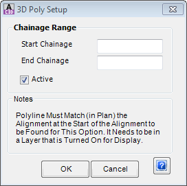
| 3D Polyline |
Click on this option to check for a 3D polyline co-incident with the alignment and read the 3D levels into the Vertical Grading.
This is automatic - if a 3D polyline is not found an error message will display 'Unable to locate 3D polyline matching alignment <Alignment Name>'
|
| Start Chainage |
Apply from start chainage |
| End Chainage |
Apply to end chainage |
| OK |
Apply and exit. |
| Cancel |
Exit the form without changing any data. |
|
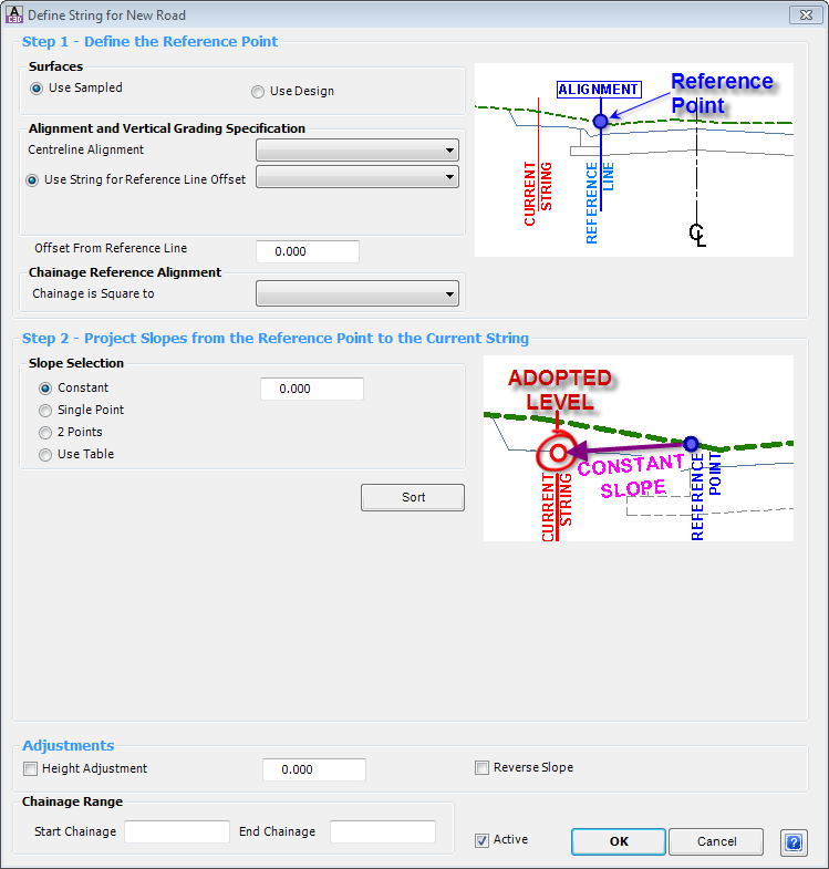
| Reference Line |
This method will create IP's at each sampled section based on selecting a Reference Point and slope projection to the current Vertical Grading. This is the most versatile option for establishing levels based on existing or design data.
There are three Steps in the process:
- Define the Reference Point: The Reference Point is used as a reference for levels and offsets to the current Vertical Grading. Designers select to extract levels from either the Design surface or the Sampled Surface, then select the method to determine the offsets. Offset and levels provide the Reference Point
- Project Slopes from the Reference Point to the Current String: Designers are able to have the software calculate slopes from the Reference Point to the current Vertical Grading based on a variety of different methods
- Apply Slope and Level Adjustments: Users can elect to add a height adjustment to the calculated levels and/or use the reverse of the calculated slopes obtained from Step 2
The calculations of the Reference Point and Projected Slopes is made at EACH sampled section and an IP level established (with an optional height adjustment).
Details of the Form and the Steps are as follows:
|
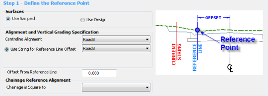
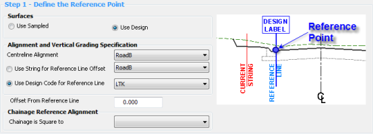
Step 1 - Define the Reference Point
|
| |
Obtain Levels for Reference Point and Slope from - options are to use the Sampled Surface or Design |
| Use Sampled |
Toggle - Levels are read from the Sampled surface in calculating the reference point and slopes (pending slope option used). Form display is as follows:
|
| Use Design |
Toggle - Levels are read from either a design String or Code in calculating the reference point and slopes (pending slope option used). Form display is as follows:
|
| |
Obtain offset for Reference Point from - here the designer specifies both the Road to use and the Alignment (or Label, pending Surface option) for the software to read the offset from and calculate a level. Options are |
| Centreline Alignment |
Use the pick list to select the Road alignment - it is usual to select the current Road |
| Use String for Reference Line Offset |
Use the pick list to select a String defining the Reference Point |
| Use Design Code for Reference Line |
When Design Surface is toggled on, the user can ALTERNATELY specify a Design Code instead of a String to determine the Reference Point.
Use the pick list to select the Road cross section Label (eg: LEB, REB, LINV, etc) to use for defining the Reference Point.
|
| Offset From Reference Line |
User can 'shuffle' the Reference Line offset using this option - type in the required value (-ve for Left and +ve for Right) |
Step 2 - Project Slopes from the Reference Point to the Current String
|
| |
Select the Slope Projection Method - toggles to select the method of calculating the slope projections from the Reference Point. The form display provides different inputs depending on the toggle option selected. |
| Constant |
Allows for the specification of a single crossfall to apply from the Reference Point to obtain levels.
Form display is as follows:
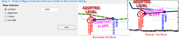
User input is as follows:
| Constant |
Type in the % slope project required |
|
| Single Point |
Calculates the Slope at a selected offset and uses the calculated slope to obtain levels.
Form display is as follows:
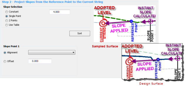
User input is as follows:
| |
Slope Point 1 - Obtain Offset/Slope from: Use the Toggle to select the required method |
| Alignment |
Use the pick list to select an alignment to determine the offset location to calculate the slope |
| Offset |
Type in a fixed offset from the Road C.L. Alignment. Convention is -ve left of the C.L. and +ve right of the C.L. |
|
| 2 Points |
Calculates the Slope between two selected offsets and uses the calculated slope between the two points to obtain levels.
Form display is as follows:
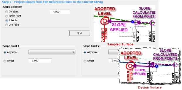
The average slope is calculated between the offset/level found for the two Slope Points and is then applied.
User input is as follows:
| |
Slope Point 1 - Obtain Offset/Slope from: This records the first offset value and then sets the level based on the Sampled Surface or Design Surface. Use the Toggle to select the required method |
| Alignment |
Use the pick list to select an alignment to determine the offset location |
| Offset |
Type in a fixed offset from the Road C.L. Alignment. Convention is -ve left of the C.L. and +ve right of the C.L. |
| |
|
| |
Slope Point 2 - Obtain Offset from: This records the second offset value and then sets the level based on the Sampled Surface or Design Surface. Use the Toggle to select the required method |
| Alignment |
Use the pick list to select an alignment to determine the offset location |
| Offset |
Type in a fixed offset from the Road C.L. Alignment. Convention is -ve left of the C.L. and +ve right of the C.L. |
|
| Use Table |
User is able to set crossfall values in a table - the software applies the selected crossfalls based on chainage and crossfall entries in the table. Interpolation occurs between the crossfall entries in the table.
Form display is as follows:
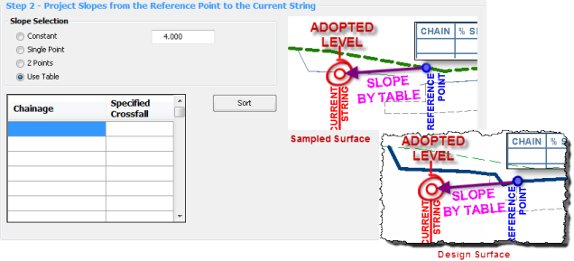
User input is as follows:
| |
Table: inputs are as follows |
| Chainage |
Type in a chainage |
| Specified Crossfall % |
Type in a crossfall value |
| |
Note: the software will interpolate crossfall values between the chainages in the table |
|
Step 3 - Apply Slope and Level Adjustments
|
| Height Adjustment |
Toggle ON if a height adjustment should be added to the calculated levels.
Type in a value to raise/lower (+ raises the IP's) the calculated levels.
|
| Reverse Slope |
Toggle ON to reverse the calculated/defined slope values and apply this to determine the calculated levels. |
| Start Chainage |
Apply from start chainage |
| End Chainage |
Apply to end chainage |
| OK |
Apply the inputs and exit the form |
| Cancel |
Exit without applying changes |
| Sort |
Sorts the chainage values in the table - only relevant when the Select the Slope Projection Method is set to Apply Slopes from a Table. |
|
| Constraints |
Click on this option to create IPs at a constraint as defined in the design data form. Form displays as follows:
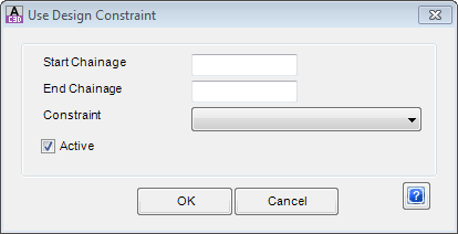
User input is as follows:
| Start Chainage |
Apply from start chainage |
| End Chainage |
Apply to end chainage |
| Constraint |
Choose a constraint that has been defined in the Design Constraints section of the Design Data form |
| OK |
Apply the inputs and exit the form |
| Cancel |
Exit without applying changes |
|
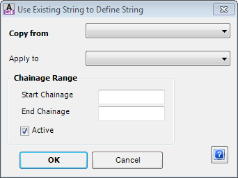
| Copy String |
This method allows the current vertical grading to be created using the vertical grading of an existing string. All the IP's (chainage and level data) on the existing string will be re-created in the current vertical grading.
|
| Copy from |
Select the String/Profile to copy the vertical design from |
| Apply to |
Select the String/Profile that you copy the vertical grading data to |
| Start Chainage |
Apply from start chainage |
| End Chainage |
Apply to end chainage |
| OK |
Apply and exit. |
| Cancel |
Exit the form without changing any data. |
|
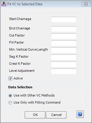
| Fit Parameters |
Although some methods, such as the Match to Existing method contain Fitting parameters, this method allows for an overall Fit/Smooth to be applied over a calculated vertical design. A calculated design might consist of a combination of multiple methods and these Fit Parameters can be added as the final method to be applied. Alternatively, this method can only be applied when the Fitting command is used.
|
| Start Chainage |
Apply from start chainage |
| End Chainage |
Apply to end chainage |
| Cut Factor |
Allows for this amount of cut against the sampled surface before inserting a new IP |
| Fill Factor |
Allows for this amount of fill against the sampled surface before inserting a new IP |
| Min. Vertical Curve Length |
Sets the minimum desired vertical curve length |
| Sag K Factor |
Vertical curve lengths will be set from this K factor in sag situations, where possible |
| Crest K Factor |
Vertical curve lengths will be set from this K factor in crest situations, where possible |
| Level Adjustment |
Lifts/lowers the outputted fitted vertical grading |
| Use with Other VC Methods |
This method will be applied at the point at which it is listed in the Vertical Grading controls list. This command will be used in conjunction with all other methods applied to create the vertical design. |
| Use Only with Fitting Command |
This method will be applied only when the Fitting command is used. |
| OK |
Apply and exit. |
| Cancel |
Exit the form without deleting any data. |
|
| From String |
Click on this option to copy another String/Profile, with the capacity to adjust the IP levels based on grade or elevation controls.
This routine was originally envisaged for road reconstruction works, where it was desired to take the design for one side of the road and project it across to the other side. The copied profile IP's and Vertical Curves are transferred to the current Vertical Grading.
At least one other profile must be available in the drawing - normally these are created from the  Create String/Profile command Create String/Profile command
Form display is (be default) as follows:
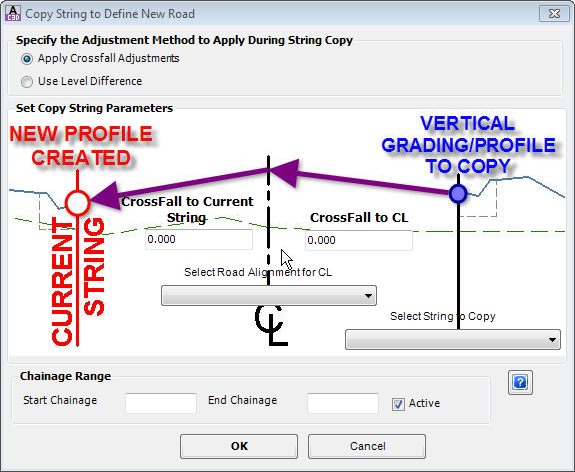
Under the heading Specify the Adjustment Method to Apply During String Copy select one of two calculation methods:
- Apply Crossfall Adjustments
- Use Level Difference
The graphic and inputs will adjust depending on the option selected.
User input is as follows:
|
| |
Apply Crossfall Adjustments: the original profile data is copied across, with the IP levels adjusted based on crossfalls from a selected profile to the current Vertical Grading |
| Select String to Copy |
Use the pick list to select the profile to copy data from |
| Select Road Alignment for CL |
Use the pick list to select a Road centreline |
| Crossfall to CL |
Type in a crossfall to adjust levels of the IP's to the CL |
| Crossfall to Current String |
Type in a crossfall from the CL to the current Vertical Grading |
| Start Chainage |
Apply from start chainage |
| End Chainage |
Apply to end chainage |
| OK |
Apply and exit. |
| Cancel |
Exit the form without changing any data. |
| |
|
| |
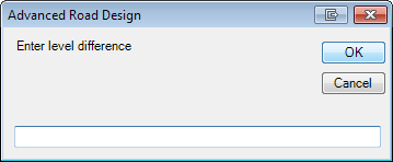
Use Level Difference: the original profile data is copied across, with the IP levels adjusted by a fixed height change |
| |
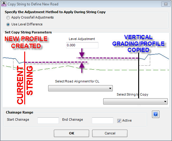 |
| Select String to Copy |
Use the pick list to select the profile to copy data from |
| Select Road Alignment for CL |
Use the pick list to select a Road centreline |
| Level Adjustment |
Type in a value to adjust the levels of the IP's copied to the current Vertical Grading |
| Start Chainage |
Apply from start chainage |
| End Chainage |
Apply to end chainage |
| OK |
Apply the profile copy to the current Vertical Grading |
| Cancel |
Exit without applying vertical grading changes |
|
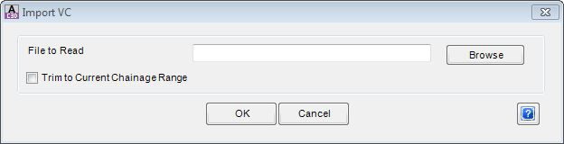
| Import / Export VC
|
The Export VC command allows the designer to export a vertical grading design to file. The file exported can be opened in a program such as Microsoft Excel to be edited. It may be required to shift the chainage of IP's - Microsoft Excel can be used to increment chainages or elevations and the edited data can be re-imported using the Import VC command.
|
| From File
|
The From File command allows the designer to import a file of vertical geometry points and create IP's and vertical curves from this data. The file should be structured as follows:
<Chainage>,<Elevation>, separated by an [Enter] per point. Save the file with extension .txt.
Example file:
0, 110
20, 95
30, 93
|
| OK |
Apply and exit. |
| Cancel |
Exit the form without deleting any data. |
|
| |
Output Tools |
This collection of commands generate outputs in the drawing as well as create volume reports |
|
 Create Surface Create Surface |
Click to create an ARD Surface of the ARD Object being graded. This surface is outputted without regard to any other ARD Object (eg: Road intersections are ignored).
The software applies the Surface Style assigned in the Active Drawing Settings - Modelling Tab.
If the rebuild mode is set to Automatic in the settings, the surface automatically rebuilds as changes are applied through the Vertical Grading Editor.
|
|
 Control Surface Display Control Surface Display |
Click to set the display options for the ARD Surface (as well as any other surfaces and model linework). The full details of this form are described in the  Toggle Display command. Toggle Display command. |
|
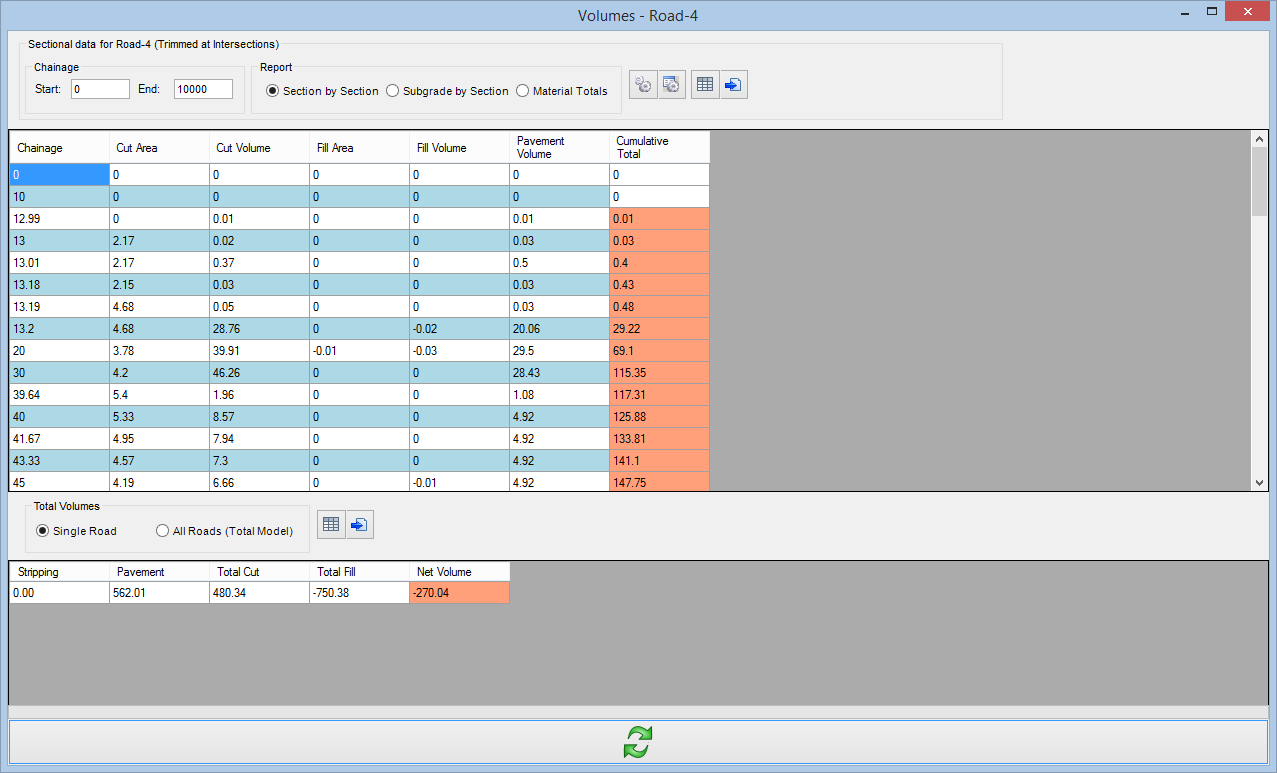
 Volume Summary Report Volume Summary Report |
Click on this icon to generate a report of the volumes. |
| |
|
 |
| |
|
The details of this form can be found in the  Volumes report command. The Volumes command interface is exactly the same, except that a third panel is also shown on the left listing all Strings for selection. Volumes report command. The Volumes command interface is exactly the same, except that a third panel is also shown on the left listing all Strings for selection. |
|
 Automatic Rebuild Automatic Rebuild |
Sets the status of automatic rebuild for linework and modelling.
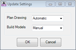
User inputs
| Plan Drawing |
To dynamically update the plan linework in the drawing set to Automatic. Set to Manual for manual updating. |
| Build Models |
To dynamically update the ARD models set to Automatic. Set to Manual for manual updating. |
| OK |
Apply and exit. |
| Cancel |
Exit the form without changing any data. |
|
| |
Update Tools |
This collection of commands ensures the vertical grading is completely updated and enables undo/redo |
|
 Undo Undo |
Undo edits in the current section |
|
 Redo Redo
|
Redo edits in the current session |
|
 Refresh Refresh |
Refreshes the display on screen - this command should not be required as most/all commands automatically result in an immediate update |
|
 Update Update
|
Updates the intersection match in levels that affect the current Vertical Grading Design as well as updating all Models (linework and surfaces). |
|
 / /  Auto Rescale Toggle Auto Rescale Toggle |
Auto Rescale On: As an IP is graphically edited, the vertical exaggeration will adjust to accommodate the new IP position
Auto Rescale Off: As an IP is graphically edited, the vertical exaggeration is not adjusted.
If screen flickering and unexpected repositioning of the IP during editing is experienced, it is recommend to turn the automatic rescaling off.
Note: When Auto Rescale is off, the middle mouse button scroll does not operate as a zoom.
|
|
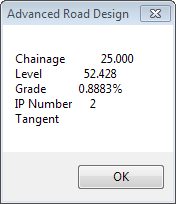
 Enquire Level Enquire Level |
This command is used to query the level at a particular chainage. Inputs are as follows:
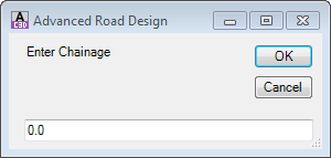 |
| Enter chainage |
Type in the chainage to report the level |
| OK |
Exit the form and display the level details at the defined chainage. Example output as follows:
|
| Cancel |
Exit the form without editing the IP's |
|
| |
Navigation Tools |
This collection of commands provide navigation of the grading window.
Note: the middle mouse button is able to be used to zoom (scroll) and pan (hold) |
|
 Zoom In Zoom In |
Zoom in by 25% |
|
 Zoom Out Zoom Out
|
Zoom out by 25% |
|
 Pan Pan |
Two button click pan. Click to select current location. Second click to move it to new location. |
|
 Zoom Extents Zoom Extents
|
Click to zoom to display the entire string on screen |
|
 Zoom Window Zoom Window |
Zoom to a window. Click and move the curser to make a 'window' selection and click again to zoom into that window |
|
 Pan to Point Pan to Point
|
Click to pan window to desired region |
|
 Show Current Extents in Plan Show Current Extents in Plan |
Zooms to the Road alignment extents in the drawing |
|
 Zoom Pipes Zoom Pipes |
Click on this button to select a pipe in the VGE and zoom to that pipe in the drawing. |
| |
|
|
|
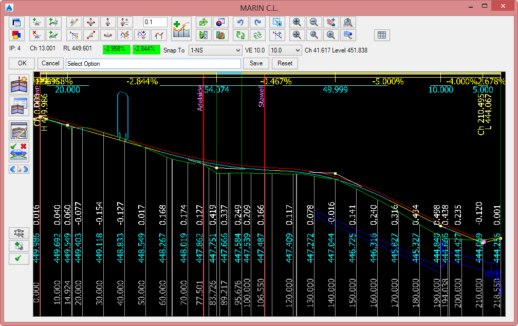
IP, Ch and RL |
Displays the IP number (1 on left incrementing to the right), chainage and RL of IP closest to mouse position |
|
 Snap To Snap To |
Sets the item to snap to when using the "Snap IP to 'Snap to' Constraint at Cross Section" or "Snap IP to 'Snap To' Constraint" options |
|
 Scale Scale |
Sets the maximum scale exaggeration of the longsection |
|
Ch, Level |
Displays the chainage and level of the mouse position in the VGE window. |
|
 |
Apply and exit the Vertical Grading Editor. |
|
 |
Exit the Vertical Grading Editor. Edits made are saved while the editor is open. Use the Undo command to undo any changes. |
|
Command Prompt |
Describes the command details and gives instruction on executing a command in the VGE. |
|
 |
Saves the current design |
|
 |
Removes all IP's except for the end points |
|
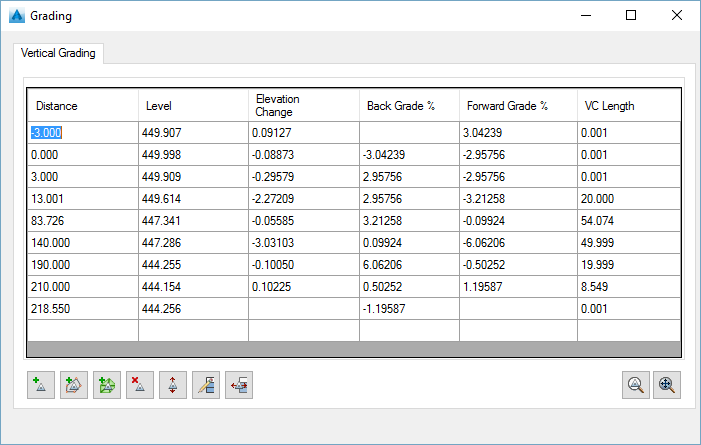
 Grid Editor Panel Grid Editor Panel |
|
| Grid View |
Displays the vertical design in a grid view. As each item is clicked on a marker is displayed in plan at the vertical IP location. List items are described below |
| Distance |
Chainage along string for IP location |
| Level |
Elevation of the IP |
| Elevation Change |
Elevation difference from the current IP to next IP |
| Back Grade % |
Grade from the current IP to the previous IP |
| Forward Grade % |
Grade from the current IP to the next IP |
| VC Length |
Type in a vertical curve length to apply at the IP. Leave at .001 for no Vertical Curve to be applied |
 Add IP by selection Add IP by selection |
Pick a location in the drawing along the grading string - an IP will be added at that location |
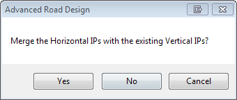
 Add IP's at horizontal geometry Add IP's at horizontal geometry |
Adds vertical IP's at horizontal geometry points along the polyline. The following form will display:
|
| Yes |
Adds extra IP's at the horizontal geometry points, keeping the existing design IP's |
| No |
Replaces the current vertical design with IP's only at the horizontal geometry points. |
| Cancel |
Do not add IP's at horizontal geometry points |
|
 Add IP's to Match Surface Levels at Selected Sections Add IP's to Match Surface Levels at Selected Sections |
Creates IP's at all sampled sections around the grading string and sets the elevation of the IP's to match the surface |
 Delete IP Delete IP |
Deletes the first highlighted IP in the grid view |
 Raise/Lower All IP's Raise/Lower All IP's |
Raises/Lowers all IP's by a user defined amount. Inputs are as follows:
|
| Input |
Type in an elevation change (positive up, negative down) |
| OK |
Apply elevation change |
| Cancel |
Do not apply and exit form |
|
 Edit Multiple IP's Edit Multiple IP's |
Select multiple rows in a column to edit that column. Options are:
| Level column cells are highlighted |
|
| Input |
Type in an elevation change (positive up, negative down) to apply to all highlighted cells |
| OK |
Apply elevation change |
| Cancel |
Do not apply and exit form |
| Grade % cells are highlighted |
|
| Input |
Type in a single grade (%) to apply to all highlighted cells |
| OK |
Apply grade (%) change |
| Cancel |
Do not apply and exit form |
| VC Length column cells are highlighted |
|
| Input |
Type in a VC length to apply to all highlighted cells. VC length will be truncated to prevent overlapping IP's or other VC's as required. |
| OK |
Apply elevation change |
| Cancel |
Do not apply and exit form |
|
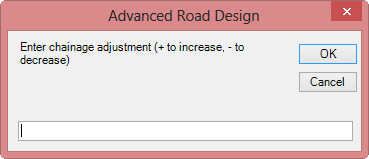
 Increment Chainages Increment Chainages |
Increments all Chainages/Stations/Distances for highlighted rows. Type in an increment and the selected IP's will be shifted by the set amount.
A warning message will display if the shift will result in IP's overlapping any vertical curves or other IP's and the edit will not be applied.
|
| Input |
Type in an increment (+ or -) to adjust the chainage/station of the highlighted IP's. |
| OK |
Apply increment to chianages/stations. |
| Cancel |
Do not apply and exit form |
|
 Zoom IP Zoom IP |
Zooms to the selected IP in the drawing |
 Zoom All Zoom All |
Zooms to the extents of the grading string |
|
| |
|
|
|
 Open Template Editor Open Template Editor |
Select this button to create/edit a typical cross section template. Full details in the Create/Edit Section Template form. |
|
 Open Design Data Form Open Design Data Form |
Select this button to access the Design Data Form. |
|
 Open Cross Section Viewer Open Cross Section Viewer |
Select this button to open an instance of the Cross Section Viewer. The designer will be prompted to select a cross section to initially load into the viewer. |
|
 Driveway Tool Driveway Tool |
Click on this option to check vehicle clearance along a driveway alignment.
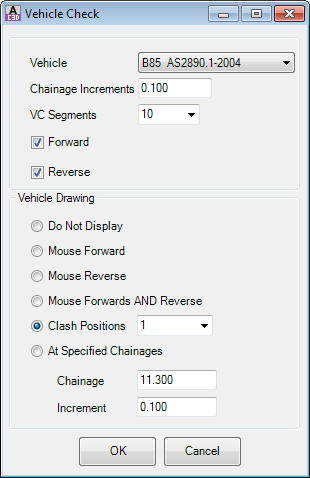
User inputs
|
| Vehicle |
Select a Vehicle Clearance Template from the pulldown menu. |
| Chainage Increments |
Sets the sampling frequency for checking clearance along the vertical grading |
| VC Segments |
Sets how the vertical curves are managed - select a number of chords to describe the vertical curve. Recommended value: 10. |
| Forward |
Checks vehicle clearance in forward direction. Calculates and displays the lowest clearance line for the vehicle path on the Vertical Grading window. |
| Reverse |
Checks vehicle clearance in reverse direction. Calculates and displays the lowest clearance line for the vehicle path on the Vertical Grading window. |
| Vehicle Drawing |
These options set what will be drawn on the screen of the Vertical Grading Editor. |
| Draw Nothing |
Show no vehicles. |
| Mouse Forward |
Places forward vehicle template in relation to mouse position on screen |
| Mouse Reverse |
Places reverse vehicle template in relation to mouse position on screen |
| Mouse Forward and Reverse |
Places forward & reverse vehicle template in relation to mouse position on screen |
| Draw at Specified Chainages |
Set the chainage to start drawing the vehicle and the increment at which the next vehicle will be drawn |
| Clash Positions |
Sets the clash position to place a vehicle at. Setting this to 2 will place vehicle at clash position 2 |
| OK |
Apply and exit. |
| Cancel |
Exit the form without changing any data. |
|
|
 Vehicle Forward Vehicle Forward
 Vehicle Reverse Vehicle Reverse
 Vehicle Move Vehicle Move
|
Toggles display depending on Vehicle Drawing options selected. |
|
 Rebuild Model Rebuild Model |
Rebuilds the model and redraws the linework - only shows if the Model/Linework udpating is set to Manual. |
|
 Rebuild Surface Rebuild Surface |
Rebuilds the surface - only shows if Surface updating is set to Manual. |
|
 Zooms to Extents of Open Cross Sections Zooms to Extents of Open Cross Sections |
Click on this button to zoom to the extents of all open cross section locations.
Before clicking
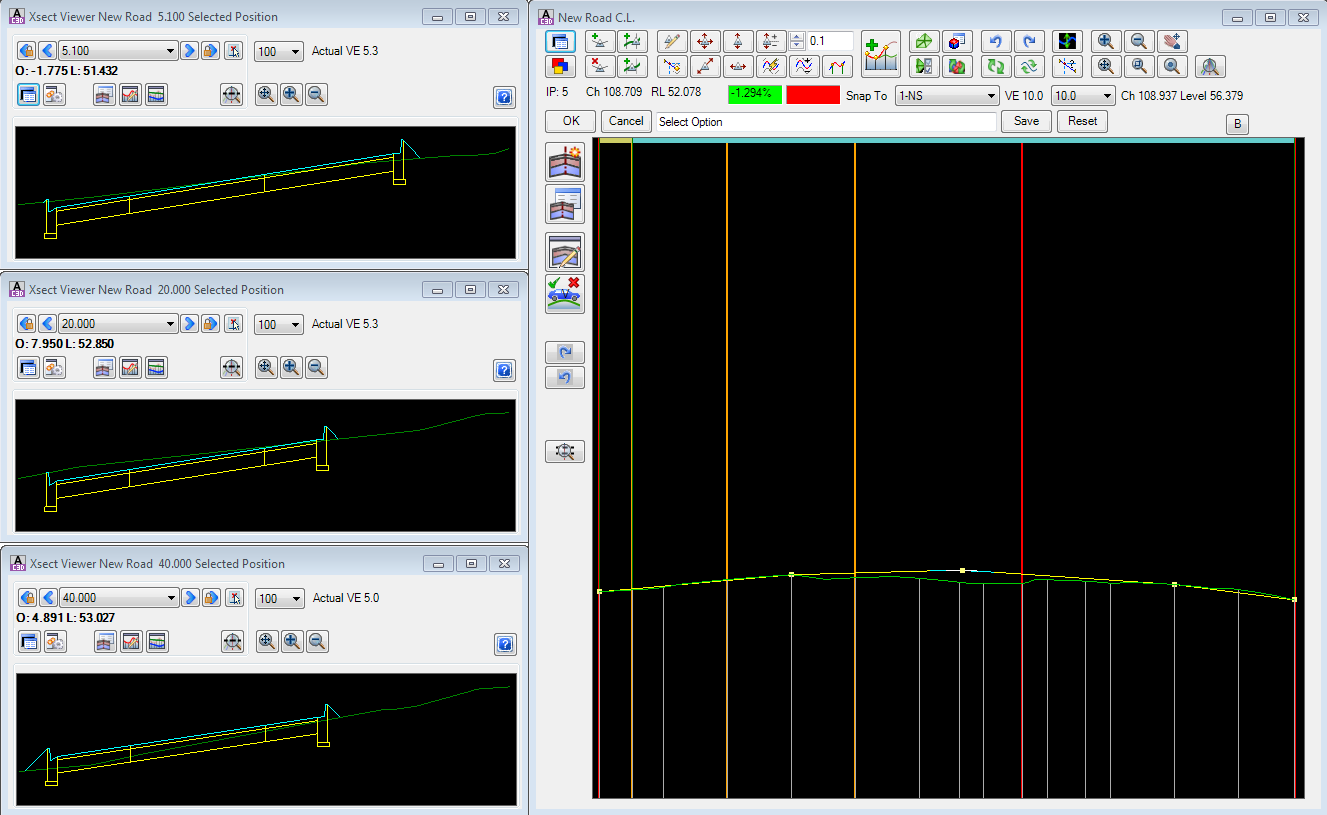
After Clicking
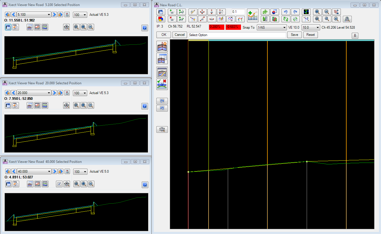
|
|
 Insert Chainages Insert Chainages |
Click on this button to add extra sampling (chainages) to the string.
Full details in the Add Extra Sections form.
|
|
 / / Auto/Manual Update Auto/Manual Update |
Tick on = auto update - editing the vertical grading automatically updates all other dependent strings and models.
Tick off = manual - editing the vertical grading will only update the cross section window displayed. Will update linework and models and other strings upon exit.
|
| |
|
|
 Create/Edit Templates form to facilitate creation/editing of cross section templates