Toggle Display
| Icon: | |
| Menu: | Surfaces > Toggle Surface Display Roads > Select/Open/Edit > Open Vertical Grading Editor Window > Control Surface Display icon |
| Ribbon: | Surfaces Tab > Utilities Panel > Toggle Display Roads Tab > Select Panel > Open Vertical Grading > Control Surface Display icon |
Introduction
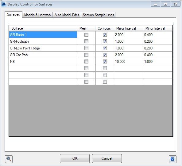
Often it is desired to quickly turn surface display on/off for major elements such as the mesh and contours, as well as to change the contour intervals. This form provides a quick method for managing the basics of surface display - this is particularly useful when there are multiple surfaces in the project.
This form enables control of surface display, the presentation and auto rebuilding of model linework, provides the ability to exclude strings from being included in the Auto Model surface or having the linework drawn, and allows string section lines to be displayed.
Surface display changes are written to the Outputs control for each surface.
This is not a modeless form, it must be closed before work can continue in the drawing.
Notes: The Auto Model command (referred to below as the Auto Model surface) is named TotalModel in the software - TotalModel is the model and surface created from running the Auto Model command.
Details
Upon selecting the command the following form is displayed:
 |
|||||||||||||||||||||
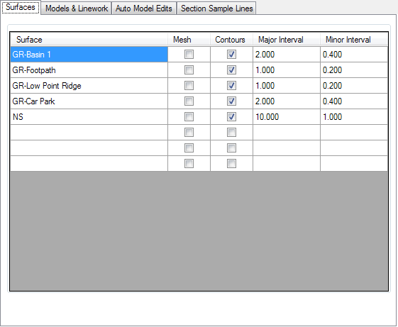
| Surfaces Tab | Lists the objects and the main toggle control options, as shown above. | ||||||||||||||||||||
|
|||||||||||||||||||||
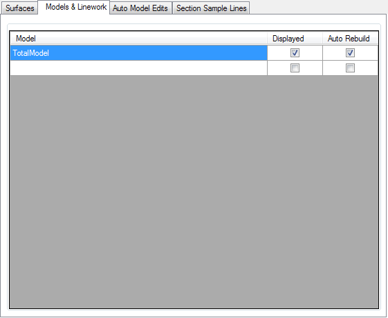
| Model & Linework Tab | Lists the objects and the main toggle control options. Tab shown below. Models and Linework equate to breaklines of features, for example, kerb lines (top, back, lip), footpaths and centrelines, etc. |
||||||||||||||||||||
|
|||||||||||||||||||||
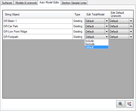
| Auto Model Edits Tab | By default, the linework for every String (and it's cross section codes) is displayed in the drawing. Auto Model only includes Road, Kerb Return, Cul-de-sac, Knuckle and Roundabout Strings. This tab provides immediate control over the strings included in the Auto Model surface, as well as what linework is displayed for the Auto Model model. | ||||||||||||||||||||
|
|||||||||||||||||||||
| Section Sample Lines Tab | Lists the String objects and the main toggle control options. Tab shown below. Sample Lines are the lines that represent the overall width of sampling taken perpendicular to the corresponding alignment string object, typically for cross section plotting purposes. |
||||||||||||||||||||
|
|||||||||||||||||||||
 Zoom and/or Pan Zoom and/or Pan |
Use the Mouse wheel to zoom and pan in the drawing. Press ESC to finish and return to the form. | ||||||||||||||||||||
| OK | Apply and exit. | ||||||||||||||||||||
| Cancel | Exit the form without making changes or use the Windows Red-X. | ||||||||||||||||||||
 Help Help |
Display Help on this command. | ||||||||||||||||||||
 Zoom Extents
 All ON
 All OFF
 Deselect All
 Invert Selection