Point Groups
Icon: |
Introduction
Point Groups provide very important functionality for managing COGO Points created in the drawing:
A Point Group can collect 'like' points together, based on a multitude of inclusion methods: Code (Description), Point Number, Elevation, coordinate range and layer
A Point Group can create a surface. When ticked on for surface creation, a Surface will be created with these COGO Points included
Users can export tables (as CAD tables in the drawing or external files) via a Point Group
Multiple edits can be made to COGO Points in a Point Group, including renumbering, editing position and changing the applied Point Style
A Point Group is used to create Survey Strings.
Any number of Point Groups can be created. By default, Point Groups are saved with the current project (-Data folder), however users can elect to save all the Point Groups to the Settings (Global) folder for default inclusion in any new project (the global Settings are copied into new projects to become the local settings).
Editing Individual Points
To edit a single point in the Point Group list use the left mouse button to double-click select the desired Pont. This will open the Edit Point form.
Point Groups and Civil 3D COGO Points
In Civil 3D, the Point Group command will also list Civil 3D Point Groups. All Civil 3D point groups are named with (Civil 3D) appended to the suffix.
Details
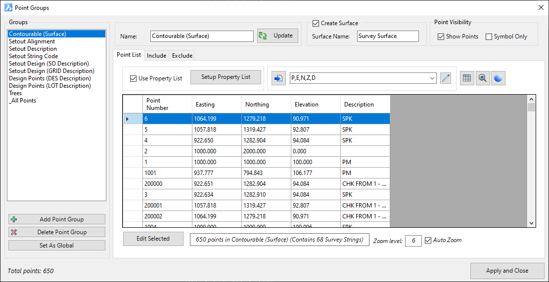
Upon selecting the command the following form is displayed:
|
|||||||||||||||||||||||||||||||||||||||||||||||
Groups |
This lists all created Point Groups and allows creation/deletion of Point Groups | ||||||||||||||||||||||||||||||||||||||||||||||
[List of Groups] |
List of created Point Groups. Click on a Point Group to set it for editing on the RHS of the form | ||||||||||||||||||||||||||||||||||||||||||||||
Add Point Group |
Click to add a new Point Group. A default Name will be assigned and this will be set on the RHS of the form for editing | ||||||||||||||||||||||||||||||||||||||||||||||
Delete Point Group |
Deletes the highlighted Point Group in the Point Group list | ||||||||||||||||||||||||||||||||||||||||||||||
Set as Global |
Edits
to Point Groups apply to the current drawing only. Click to set all Point Groups in the current drawing as the 'Global' Point Group list. This will overwrite the current Point Group settings in the Settings folder and repace with the ones established here. Individual points are not included. A confirmation message will display to set these as the global/default - yes to overwrite or no to retain the current default Point Groups. |
||||||||||||||||||||||||||||||||||||||||||||||
| The Right Hand Side of the form provides functionality to edit the selected Point Group in the Point Group List | |||||||||||||||||||||||||||||||||||||||||||||||
| Name | Type in a name for the Point Group. As a name is typed it will edit the saved Point Group name | ||||||||||||||||||||||||||||||||||||||||||||||
| Update | Click to update the Point Group, in the event that points have been added/removed from the list following editing in this form | ||||||||||||||||||||||||||||||||||||||||||||||
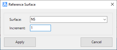
Create Surface |
This allows users to create a Surface inclusive of all points in this Point Group | ||||||||||||||||||||||||||||||||||||||||||||||
Create Surface tick box |
Tick on to create a surface | ||||||||||||||||||||||||||||||||||||||||||||||
Surface Name |
Type
in a name for the surface to create. Note: It is highly recommended that every Surface name in each Point Group is unique to prevent overwriting or other unintented results. |
||||||||||||||||||||||||||||||||||||||||||||||
Point Visibility |
Set the display of the point on/off, or turn the text element/s on/off | ||||||||||||||||||||||||||||||||||||||||||||||
Show Points |
Tick on to show the points of the point group in the drawing | ||||||||||||||||||||||||||||||||||||||||||||||
Symbol only |
Tick on to hide the Text for all points in the point group. Blocks and other objects used in the Point Style will still be shown. | ||||||||||||||||||||||||||||||||||||||||||||||
Points List Tab |
This tab displays all points that belong in the group. Points in the group can be edited via this tab | ||||||||||||||||||||||||||||||||||||||||||||||
 |
|||||||||||||||||||||||||||||||||||||||||||||||
Use Property List |
Tick
on to enable control of what columns are displayed in the points
list, as well as the column names. Note: The columns set here are used for the CAD Table output only. Output to external files is handled by the selected Point Format. |
||||||||||||||||||||||||||||||||||||||||||||||
Setup Property List |
See
the Point
Property List help for full details on these controls. The Point Property List lets users establish what Properties (fields) of information are stored for a COGO Point. Some fields (Properties) are core fields that every Point needs such as: number identification (Point Number), position (Easting, Northing, Elevation), description, scale and rotation. Other Properties may be relevant based on what data is associated with the point (for example, the point may be obtaining it's position from an alignment or string, so users may wish to add the alignment name, offset or other information on the point). Some Properties may be completely managed by the user. Note: For information to display for the Points, each individual point must have a matching Point Property. This is usually inherited from the Point Style assigned by the Point Code Set when the point is created. |
||||||||||||||||||||||||||||||||||||||||||||||
| |
Click
here to create an external file. The format of the
file is managed by the selected Point
Format (picklist to the right of this Export to File button). Pending the file format, the software will open the file to the native software set to open the file (eg: by default, .csv files will open in Microsoft Excel) |
||||||||||||||||||||||||||||||||||||||||||||||
Edit Point Formats |
This opens the Point Formats form for creating/editng/managing point formats. | ||||||||||||||||||||||||||||||||||||||||||||||
| Point Format Pick List | Pick list of Point Formats. This establishes the point properties to include in the output file as well as the delimeter between fields. | ||||||||||||||||||||||||||||||||||||||||||||||
|
|
Click
here to create a Table in the drawing. The points as
displayed in the Point List will be used for the table (column
headings and precision of the cells). The user will be prompted to select a location in the drawing to create the table (top left corner). |
||||||||||||||||||||||||||||||||||||||||||||||
|
|
Click
here to display all points in the selected Point Group. The
following form will display: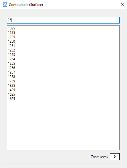 Type in a point number to filter the list of points. Click on a point in the list to zoom to the point in the drawing. Zoom level sets the amount of zoom to apply. |
||||||||||||||||||||||||||||||||||||||||||||||
|
|
Click
here to export both the Points and Survey Strings to KML, and open in
Google Earth Pro (if installed). Upon starting the command the following form will be displayed:
If Google Earth Pro is installed, it will be opened and displayed. |
||||||||||||||||||||||||||||||||||||||||||||||
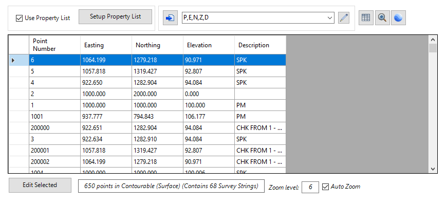
[Points List] |
This
lists all the Points that are included in the Point Group. Users
can select point/s in the list for editing (deleting, changing
style, editing position, renumbering). Left click on a Point in the list to zoom to it in the drawing. Zoom scale is set by the Zoom Level. Double click on a Point to open the Point Editor for the point. Use the left mouse, while holding down [Shift] or [Ctrl] to select multiple points for edits to be applied. |
||||||||||||||||||||||||||||||||||||||||||||||
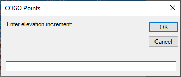
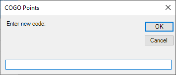
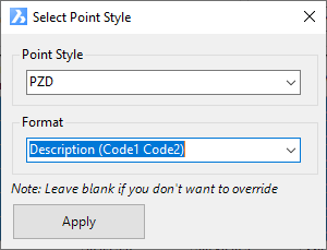
Edit Selected |
Provides
edits that can apply to all Points in the point group (if none
or only one id highlighted) or to multiple points that are highighted
by the user. When an edit command is started, the user will need to confirm whether to proceed. Users can continue with the edit or Cancel and highlight multiple points to change. Edits are as follows:
|
||||||||||||||||||||||||||||||||||||||||||||||
Display Panel |
Displays information about the Point Group (total number of points in group) | ||||||||||||||||||||||||||||||||||||||||||||||
Zoom Level |
When points are selected in the Points List, the software zooms to them in the drawing. The Zoom Level controls how 'zoomed in' the drawing is to the point. A small number zooms in close and a large number zooms out. | ||||||||||||||||||||||||||||||||||||||||||||||
Auto Zoom |
Untick to stop Auto Zoom when points are selected in the Points List. | ||||||||||||||||||||||||||||||||||||||||||||||
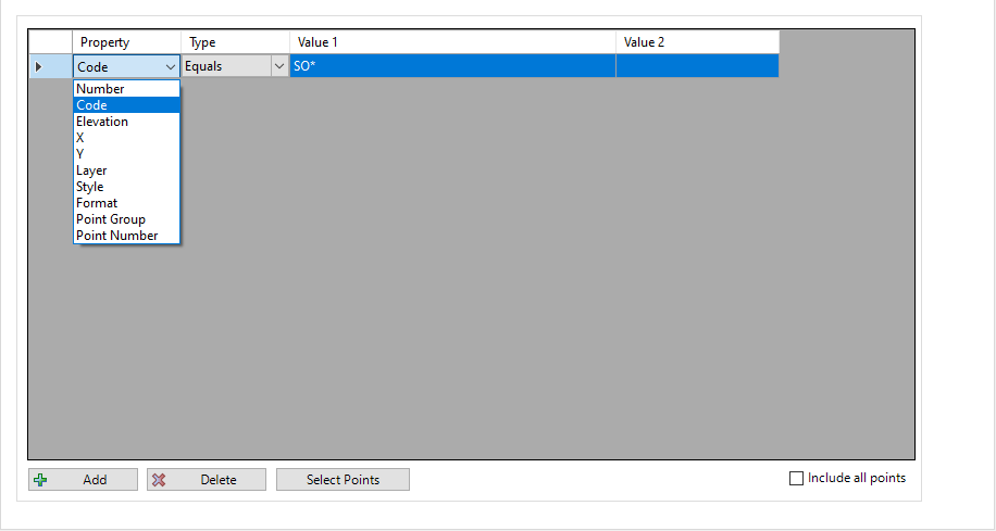
Include Tab |
Select the conditions for adding COGO Points to the group. | ||||||||||||||||||||||||||||||||||||||||||||||
 |
|||||||||||||||||||||||||||||||||||||||||||||||
Property Column |
After
using Add to add an entry, users can pick from the list of Point
Properties to use as a filter. Typical properties include: Point Number, Code, Elevation, Easting (x), Northing (y), Layer, Style, Format, Point Group, however the list is appended by the properties set in the Setup Property List for the Point Group. |
||||||||||||||||||||||||||||||||||||||||||||||
Type Column |
This sets how to apply the Property selected. The types include: Equals (good when matching Point Descriptions), Greater than (good for numeric properties such as elevation), Less than ((good for numeric properties such as elevation) and Between (good for numeric properties such as elevation) | ||||||||||||||||||||||||||||||||||||||||||||||
Value 1 |
Input the value for determining inclusion of Points that meet the criteria | ||||||||||||||||||||||||||||||||||||||||||||||
Value 2 |
Only applies if the Type is set to Between. This is the second value to be beween (it is programmed for Value 1 to be the lower bound and Value 2 to be the upper bound) | ||||||||||||||||||||||||||||||||||||||||||||||
Add |
Adds
an entry (filter criteria). Once added, the inputs
can be edited directly in the filter list. Note: Each criteria forms part of an 'OR' boolean statement - each criteria that is met will add all Points that meet the condition. |
||||||||||||||||||||||||||||||||||||||||||||||
Delete |
Remove a selected entry (filter criteria) | ||||||||||||||||||||||||||||||||||||||||||||||
Select Points |
Click to select points directly in the drawing. Click to add entry/ies with Point Numbers based on the selections. Each point is added to the list with a 'Number' filter Property. | ||||||||||||||||||||||||||||||||||||||||||||||
Include All Points |
Tick
on to Include every Point in the Point Group. Note: The Exclude list is used to remove points from the Include list. |
||||||||||||||||||||||||||||||||||||||||||||||
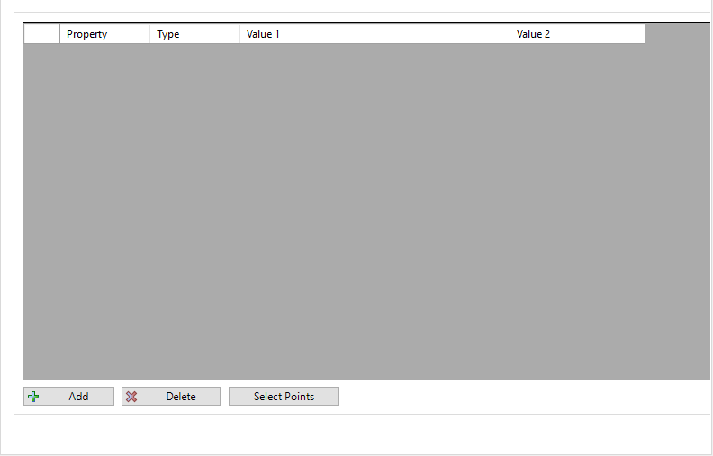
Exclude Tab |
Select the conditions for excluding (removing) COGO Points from the group. | ||||||||||||||||||||||||||||||||||||||||||||||
 |
|||||||||||||||||||||||||||||||||||||||||||||||
Property Column |
After
using Add to add an entry, users can pick from the list of Point
Properties to use as a filter. Typical properties include: Point Number, Code, Elevation, Easting (x), Northing (y), Layer, Style, Format, Point Group, however the list is appended by the properties set in the Setup Property List for the Point Group. |
||||||||||||||||||||||||||||||||||||||||||||||
Type Column |
This sets how to apply the Property selected. The types include: Equals (good when matching Point Descriptions), Greater than (good for numeric properties such as elevation), Less than ((good for numeric properties such as elevation) and Between (good for numeric properties such as elevation) | ||||||||||||||||||||||||||||||||||||||||||||||
Value 1 |
Input the value for determining inclusion of Points that meet the criteria | ||||||||||||||||||||||||||||||||||||||||||||||
Value 2 |
Only applies if the Type is set to Between. This is the second value to be beween (it is programmed for Value 1 to be the lower bound and Value 2 to be the upper bound) | ||||||||||||||||||||||||||||||||||||||||||||||
Add |
Adds
an entry (filter criteria). Once added, the inputs
can be edited directly in the filter list. Note: Each criteria forms part of an 'OR' boolean statement - each criteria that is met will add all Points that meet the condition. |
||||||||||||||||||||||||||||||||||||||||||||||
Delete |
Remove a selected entry (filter criteria) | ||||||||||||||||||||||||||||||||||||||||||||||
Select Points |
Click to select points directly in the drawing. Click to add entry/ies with Point Numbers based on the selections. Each point is added to the list with a 'Number' filter Property. | ||||||||||||||||||||||||||||||||||||||||||||||
Total Points |
Information field describing the total number of COGO Points in the drawing | ||||||||||||||||||||||||||||||||||||||||||||||
Apply and Close |
Apply any changes to the Point Groups and close the form. | ||||||||||||||||||||||||||||||||||||||||||||||