Create Survey Strings
Icon: |
Introduction
This command creates linework connecting COGO Points by joining points in a select Point Group. Civil 3D or Civil Site Design COGO points and point groups can be used to create Survey Strings.
In order for this command to run the user needs to specify two things:
The points to include. This is done by selecting a Point Group.
The point descriptions to use for creating linework, including 2D polylines, 3D polylines and surface breaklines. This is managed by a Survey Line Set Table.
It is usual to initially join common points in sequential (point number) order. Users can elect instead to connect points in the order that they were created (order of points in the imported points file, if Import Points is used to create the Civil Points)
The Survey String Manager form can be used to edit the order of joining COGO Points, for the case that points have been picked up 'out of sequence'.
Civil 3D Users and Point Groups
All Civil 3D point groups listed are named with (Civil 3D) appended to the suffix.
Civil 3D Users and Large Point Numbers
Programatically, it is not possible to edit Civil 3D COGO point numbers when the point number exceeds 2147483647. For these cases, the software can be set to read and write to the Civil 3D Point Name property for creating Survey Strings, instead of Point Number.
Note: If 'Point Name' is used to manage the Civil 3D points, do not change the Civil 3D Point Number.
Details
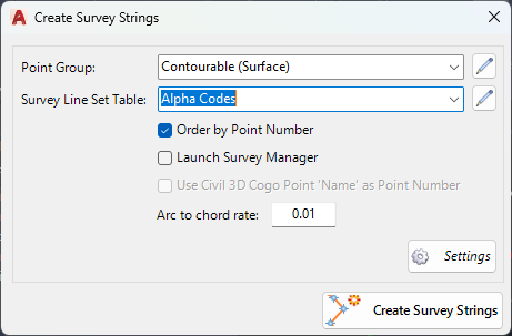
Upon selecting the command the following form is displayed:
|
|||||||||||||||||||||||||||||||||||||||||||||||
Point Group |
Select a Point Group for the list of Civil Points that should be connected with survey lines. | ||||||||||||||||||||||||||||||||||||||||||||||
Survey String Set Table |
Select a Survey Line Table that describes which Codes (point descriptions) should be connected with Survey Stringwork. | ||||||||||||||||||||||||||||||||||||||||||||||
Order by Point Number |
Tick on to connect Survey Strings by ascending point number, per Point Description. | ||||||||||||||||||||||||||||||||||||||||||||||
Launch Survey Manager |
Tick on to open the Survey Line Manager form immediately upon creation of the Survey Lines. | ||||||||||||||||||||||||||||||||||||||||||||||
Use Civil 3D Cogo Point 'Name' as Point Number |
Tick
on to read the Civil 3D Point Name property for creating Survey
Strings. Note: Only enabled in Civil 3D. |
||||||||||||||||||||||||||||||||||||||||||||||
Arc to Chord rate |
Type in a value for the offset distance between a true arc between points and the chords around that arc. Chords are created to support surface triangulations. | ||||||||||||||||||||||||||||||||||||||||||||||
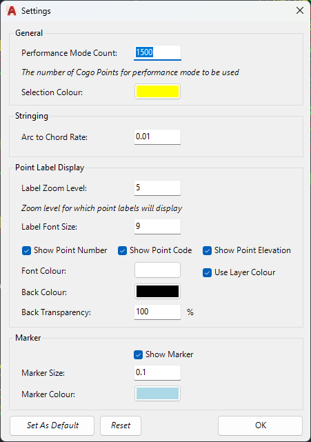
Settings |
Establishes display and performance settings for the Survey Line
Manager. The following form will display:
|
||||||||||||||||||||||||||||||||||||||||||||||
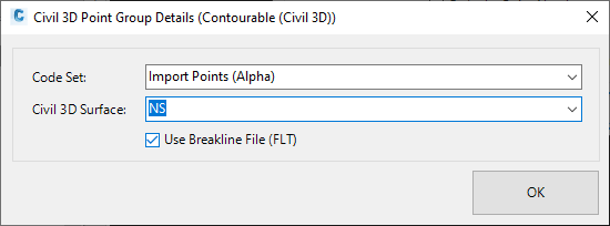
Create Survey Strings |
Creates
linework in the drawing connecting the Civil Points contained
in the selected Point
Group and as per the Survey
Line Table. Note: Civil 3D users will be prompted to confirm the surface to add Breaklines to, where the Code/s have been set to create a Breakline as per the Survey Line Table. The following form will display:
|
||||||||||||||||||||||||||||||||||||||||||||||