Point Styles
Icon: |
|
Introduction
Using Point Styles, a user can choose and alter the look and behaviour of their COGO Points.
Point display is managed by applying Point Styles to the Points. A Point Style consists of:
-
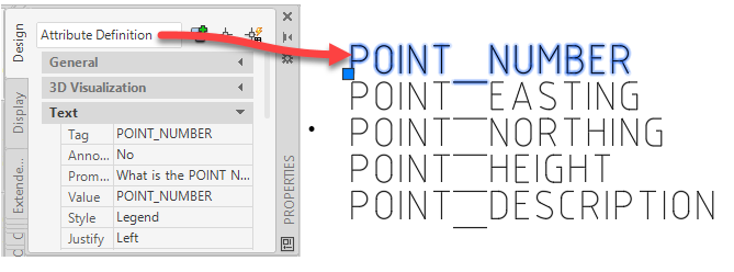
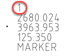
A Drawing File (.dwg). This Drawing File (Block) describes the way you want the object to look (the symbol representing the type of point) as well as the label (the text fields that describe details about the point). Each text field is created as Attributed Definition text. Dynamic blocks are supported.
-
Point Properties. This is the list of fields that can be stored on the point. Some poperties (fields) are essential: number, easting, northing, elevation. Some property fields are optional: chainage, offset. Some property fields are user defined and managed.
-
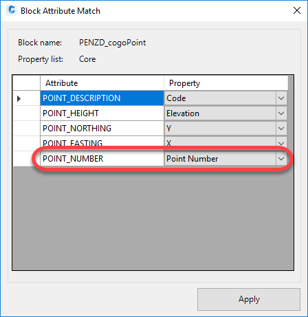
Assigning Point Properties to Attributed Text fields. Information such as point number, easting, northing, elevation are assigned to created Attributed Definition Text in the selcted drawing (block).
-
CAD Point (this is optional). A CAD Point can be included at the point insertion, along with the Block.
1. Create a CAD Drawing containing the symbol and (attributed) text required |
2. Assign Point Properties to the Attributed Text |
3. Create Points
|
 |
 |
 |
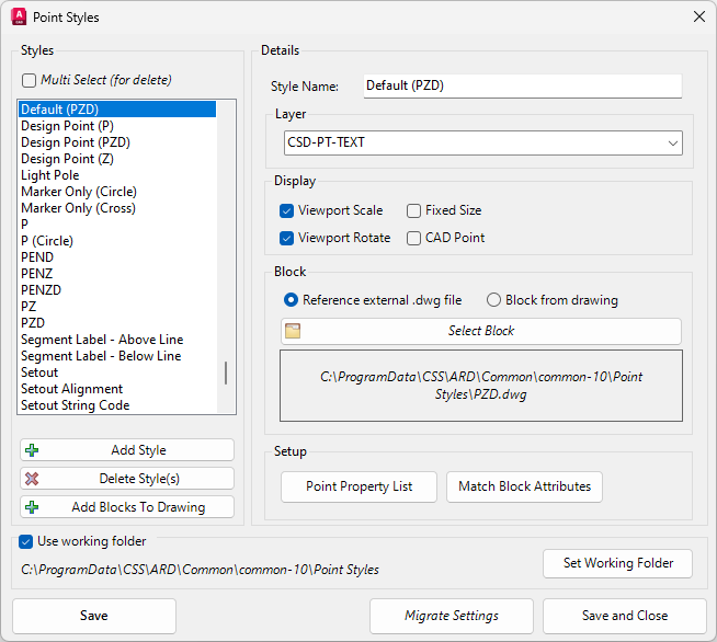
Details
Setting the Point Style is how you can link a Block to a Layer, specify the Point Properties from the Point Properties List and then match them to a Block's Attributes. Optionally attaching a CAD Point also makes the point available for use in the creation of Surfaces. Upon selecting the command the following form is displayed:
|
|
|||||||||||||
|
Styles |
This frame lists the Point Styles sorted numerically first, then alphabetically. The more commonly used Point Styles have been created for the user but these can be edited, added to, or deleted as preferred. |
||||||||||||
| Multi Select (for delete) |
Tick On Multi Select (for delete) to select multiple point styles. Note: Only works for Delete Styles. |
||||||||||||
 |
Click this button to add a new Point Style. You can then Name and apply settings to your new Point Style in the adjacent Details panel. | ||||||||||||
 |
To remove a Point Style, highlight it in the list and click the Delete Style button. Confirm your choice by clicking Yes. | ||||||||||||
|
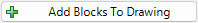
|
Click Add Blocks To Drawing to add the Blocks in the Point Styles to the current drawings Block Library. |
||||||||||||
|
Details |
Set the details of your Point Style in this panel. |
||||||||||||
|
Style Name |
Name your style in this field. It is recommended to use a name that describes the Point Style so you and other users can identify the settings later. |
||||||||||||
|
Layer |
This frame sets the assigned Layer for the Blocks created using this Point Style. |
||||||||||||
|
Layer Dropdown |
Click on the Layer Dropdown and select the preferred layer. Some of the objects in the preset Blocks will adopt the properties of the selected layer including colour and linetype. |
||||||||||||
|
Display |
Optionally choose how the COGO Point will be represented. |
||||||||||||
|
Viewport Scale |
Tick on to allow COGO points to automatically resize and in any Viewport, to match the original size of the COGO Point (resizing to display at 1:1 in Paper Space). If unticked, COGO points will scale between Model Space and the Viewport as per non-annotative text/blocks. Note: This control can be globally disabled via the Resize and Layout Settings form. |
||||||||||||
|
Viewport Rotation |
When unticked, COGO points will be rotated in Viewports to always show horizontal to the Layout sheet When ticked, COGO points will rotate to match the Viewport rotation. Note: This control can be globally disabled via the Resize and Layout Settings form. |
||||||||||||
|
CAD Point |
Check this box to represent your COGO Point with an additional AutoCAD/BricsCAD point. This point can then be used for surface creation in COGO Site Design Surfaces. |
||||||||||||
|
Fixed Size |
Tick on to include the point symbol at the created size of the original block. When unticked, the point size will be adjusted based on the drawing scale (for both the model and viewports in layout tabs). |
||||||||||||
|
Block |
This frame identifies the Block to be associated with the Point Style. |
||||||||||||
| Reference external .dwg file | Tick On to specify that the block for the selected Point Style is loaded from an external drawing file. | ||||||||||||
| Block from drawing |
Tick On to specify that the block for the selected Point Style is loaded from current drawing. Note: Block must exist in drawing. If switching block source from Reference external .dwg file to Block from drawing, it is recommended to run the Add Blocks to Drawing command first. |
||||||||||||
|
|
Click this button to browse Windows to select your Block to be associated with the Point Style. The currently selected Block and it's location is listed adjacent. Users can select from the preset Blocks or create their own and save them to the Working Folder for selection. |
||||||||||||
|
Setup |
This frame contains the controls for your Point Property List and Match Block Attributes. |
||||||||||||
| |
See the Point Property List help for full details on these controls. Click here to select and adjust the Point Properties available to be linked to the Attributes of the selected Block. You can create your own custom Properties if preferred. |
||||||||||||
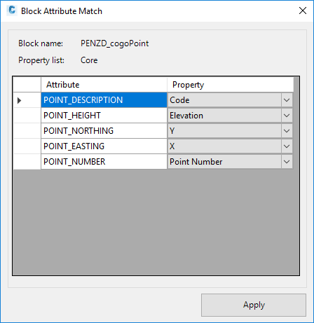
|
|
Click here to link the Point Properties to the Attributed Definition text inside the selected CAD Block. At the time of creating a Point, the Point Property input will be used to overwrite the Attributed Definition text field.
|
||||||||||||
|
Use Working Folder |
This panel names the Working Folder. Tick on Use Working Folder to change the folder for the save location of the blocks. |
||||||||||||
|
Set Working Folder |
Tick this on to use the listed Working Folder. This sets a fixed location for the point blocks. The path will be listed. By default, blocks must be stored in the Settings folder, in a folder named Point Styles. Clicking on the path named next to the Set Working Folder button will open to the Settings folder location. |
||||||||||||
| Save | Save your changes and keep the form open. | ||||||||||||
| Migrate Settings | Migrate point settings from legacy Stringer Topo. See Migrate Stringer Points. | ||||||||||||
|
Save and Close |
Saves your changes and exits the form. |
||||||||||||