Point Code Set
Icon: |
Introduction
Point Code Sets allow users to apply a Point Style, override the layer for the point and format the Point Description when points are created, based on finding a matching Point Code (Description) in the selected Point Code Set. All Point creation commands include a Point Code Set for establishing Point Styles based on the point description. If a point Description is matched in the Point Code Set, this will always govern the assignment of the point style and layer for the COGO Point.
Point Code Sets are extremely useful when importing a file of points with multiple descriptions - the Code Set will sort through all the descriptions and assign Point Styles and add the points to layers based on the description of each point.
Any number of Point Code Sets can be created. By default, Point Code Sets are saved with the current project (-Data folder), however users can elect to save all the Point Code Sets to the Settings (Global) folder for default inclusion in any new project (the CSD Settings are copied into new projects to become the local settings).
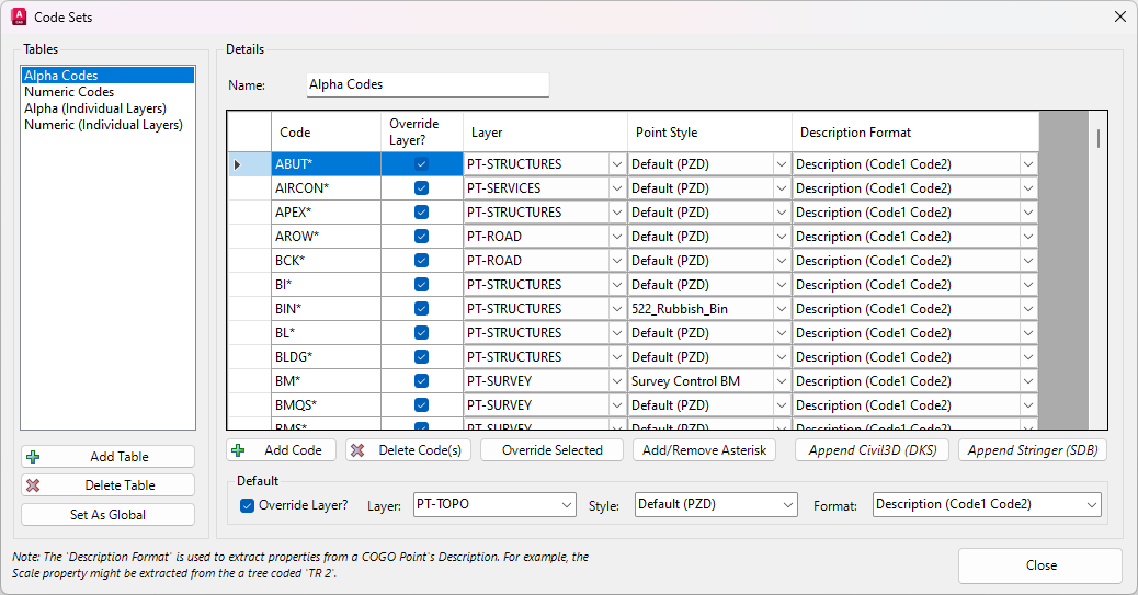
The form is split into two sections: the left side is listing the Point Code Sets (with ability to create and delete Code Sets), and the right side provides editing functionality for the selected Point Code Set.
About the Description Format
The incoming Point Description can be formatted by applying a Description Format.
For example, the full description may contain the Code (type of object), the intended Scale of the point and the intended Rotation of the point, separated by a delimiter (such as a space). Once the full description has been formatted and the 'components' of the description extracted, they can be used to adjust the scale, rotation and other aspects of the Point output.
An imported point with description of, say TR 5 45, could be interpreted by the software in the following way:
-
The point Code is TR so should have a 'tree' Point Style assigned
-
After the space, the 5 represents the diameter/radius of the tree so should be considered as the Scale to apply to the Point (this would be the User Scale point parameter)
-
After the next space, the 45 represents the rotation of the tree (relative to the WCS) so should be considered as the Rotation to apply to the Point (this would be the User Rotation point parameter)
The Description Format is managed by the user selecting a Point Format, which details the Properties of each part of the Description and the delimeter between properties.
IMPORTANT: Point Formats are used for three purposes:
-
To describe the columns of data in an incoming file, as they should apply to the properties assigned to created points (this for would be for parameters such as point number, easting, northing, elevation, full description)
-
To format the full Description of a point after it is inserted in the drawing, to assign additional parameters based on the format of the Description (as described above)
-
To describe the columns of data for exporting Points to an external file. Typically this would match up with the format used for importing files, however could also include parameters such as chainage, offset, alignment that could be stored on a point representing a string design
It is strongly recommended to name the Point Formats based on their intended use - unexpected results will occur if a Point Format is applied for a different use to that intended (in this case, only Point Formats that describe the way the point Description should be formatted should be applied). A number of default Point Formats are created with this intent - they all start with the name 'Description'.
Details
Upon selecting the command the following form is displayed:
|
|
|||||||||||||||
|
Tables |
This lists all created Point Code Sets and allows creation/deletion of Point Code Sets | ||||||||||||||
|
[List of Tables] |
List of created Point Code Set tables. Click on a Point Code Set to set it for editing on the RHS of the form | ||||||||||||||
|
Add Table |
Click to add a new Point Code Set. A default Name will be assigned and this will be set on the RHS of the form for editing | ||||||||||||||
|
Delete Table |
Deletes the highlighted Point Code Set table in the Point Code Set list | ||||||||||||||
|
Set as Global |
Click to set all Point Code Sets as the 'Global' Point Code Set list. This will overwrite the current Point Code Set settings in the CSD Settings folder and replace with the ones established here. A confirmation message will display to set these as the global/default - yes to overwrite or no to retain the current default Point Code Sets. |
||||||||||||||
|
Details |
The Right Hand Side of the form provides functionality to edit the selected Point Code Set in the Point Code Set List | ||||||||||||||
| Name | Type in a name for the Point Code Set. As a name is typed it will edit the saved Point Code Set name | ||||||||||||||
| Code column | Type in Codes to match with. The Code is the full Point Description. Use a Wildcard (*) to allow for any characters preceding/succeeding the required Code. Note: The inputs here are CASE SENSITIVE, so 'TR' is not the same a 'tr' |
||||||||||||||
| Override Layer? column | Tick on to override the default layer (as defined in the Point Style) for the Point to be created on. This allows for the same Point Style to be used for multiple codes, with the insertion layer managing the user identification of the points. | ||||||||||||||
| Layer column | If Override Layer is ticked on, this picklist of layers can be used to set the Layer to place the point on, where the Description matches with the Code cell. Note: The pick list contains only layers that exist in the drawing. It is assumed that all layers are creating in the drawing and available to use. If selected layer is not in the drawing, expect this to default to layer 0. |
||||||||||||||
| Description Format column | The incoming Point Description can be formatted by applying a Description Format. The Description Format is managed by the user selecting a Point Format using the pick list. | ||||||||||||||
|
Add Code |
Click here to add a Code to the list. The Code is added to the bottom of the list and given the Code 'Unnamed', defaulting to layer zero and applying the first found Point Format. Edit in the list once added. | ||||||||||||||
|
Delete Code |
Deletes highlighted codes in the list. | ||||||||||||||
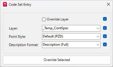
| Override Selected |
Override the Layer, Point Style, Description Format and/or Override Layer values for highlighted codes. Upon running this command the following form is displayed:
|
||||||||||||||
| Add/Remove Asterisk | Add or Remove the trailing * (asterisk) from highlighted codes in list. | ||||||||||||||
|
Paste from Civil3D (DKS) |
Civil 3D has a Description Key Set, which provides similar functionality to the Point Code Set for automating the display and presentation of points based on their descriptions. Users can highlight all codes in the Description Key Set, choose Copy to Clipboard, then click on this button to paste from clipboard to create Codes. The Code, Layer and Point Style columns can be applied (where the names match with layers and Point Styles). |
||||||||||||||
|
Add from Stringer (SDB) |
If Stringer Topo (for AutoCAD or BricsCAD) is
installed, then the contents of the Stringer Settings tables (.sdb files) can be
used to populate the Point Code Set table. After clicking on the button, users
will be able to navigate to and select a Stringer .SDB file. All Codes will be
added from the .SDB as well as: - The layer (where the layer names in the SDB file exactly match with CAD layers in the drawing. If there is no match then layer 0 is used), and - Point Style (where the Point Style name in the SDB matches a Point Style name in in Point Styles form, the matching Point Style will be assigned. Otherwise the Default Point Style will be assigned). |
||||||||||||||
|
Default |
Defaults to apply for points created with descriptions not in the list | ||||||||||||||
| Override Layer? | If unticked, points will be created on the current drawing layer. If ticked, layer assignment will be as per the layer picklist. | ||||||||||||||
| Layer? | Pick a default layer | ||||||||||||||
| Style | Pick a default point style | ||||||||||||||
|
Format |
Pick a default point description Format | ||||||||||||||
|
Close |
Closes the form. | ||||||||||||||