|
|
|
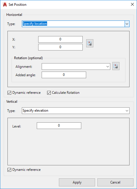
Horizontal
|
Set up the horizontal positioning of the object |
|
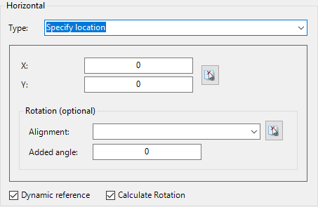
Type
|
Sets the method for setting up the horizontal position. Options include: |
|
Specify Location
|
|
x,y position is set by the user.
|
|
X
|
Type in an x position or click on the button to select from the drawing |
| Y |
Type in a y position or click on the button to select from the drawing |
|
Rotation (optional)
|
The rotation of the item can be set to an alignment in the drawing |
|
Alignment
|
Select alignment from the dropdown or use the pick button to enable selection from the drawing |
Added Angle
|
Type an angle in degrees for additional rotation
|
|
|
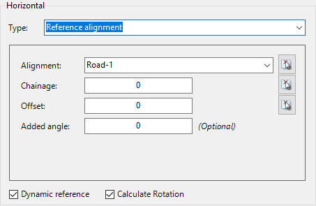
Reference Alignment
|
|
Position is set relative to an alignment
|
|
Alignment
|
Select alignment from the dropdown or use the pick button to enable selection from the drawing |
|
Chainage
|
Distance along the alignment. Use the pick butotn to select from teh drawing |
|
Offset
|
Type in an offset from the alignment |
Added Angle
|
Orientation will be taken from the alignment if 'Calculate Rotation' is ticked on. This adds an angle, in degrees, to the item
|
|
|
|
|
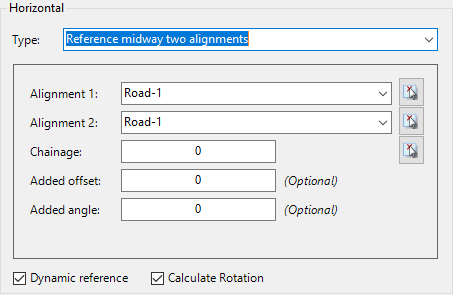
Locates the item midway between two alignments in the drawing
|
|
Alignment 1
|
First alignment for calculating midway point. Use pick button to select from the drawing. |
| Alignment 2 |
Second alignment for calculating midway point. Use pick button to select from the drawing. |
| Chainage |
Distance along the first alignment. Distance is measured perpendicular to the first alignment at this point, and the midway point calculated. Use pick button to select from the drawing. |
| Added offset |
Type in a value to move along the perpendicular line, -ve left or and +ve right of the midway point |
| Added angle |
Orientation will be taken from the alignment if 'Calculate Rotation' is ticked on. This adds an angle, in degrees, to the item
|
|
|
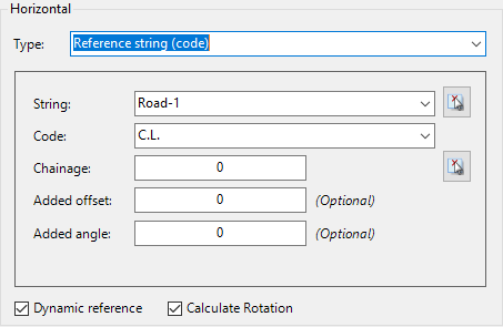
Reference String (code)
|
|
Uses a Code for the horizontal position
|
|
String
|
Select a designed string |
| Code |
Select a code along the String to use for the horizontal position |
|
Chainage
|
Distance along the first alignment. Distance is measured perpendicular to the first alignment at this point, and the midway point calculated. Use pick button to select from the drawing. |
| Added offset |
Type in a value to move along the perpendicular line, -ve left or and +ve right of the midway point |
| Added angle |
Orientation will be taken from the alignment if 'Calculate Rotation' is ticked on. This adds an angle, in degrees, to the item
|
|
|
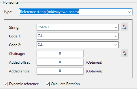
Reference String (midway two codes)
|
|
Finds the midpoint between two codes on a String (such as the centreline and left edge of road) for the position
|
|
String
|
Select a designed string |
| Code 1 |
First code for calculating position |
| Code 2 |
Second code for calculating position. Midpoint is found between the two codes at the selected chainage. |
|
Chainage
|
Distance along the first alignment. Distance is measured perpendicular to the first alignment at this point, and the midway point calculated. Use pick button to select from the drawing. |
| Added offset |
Type in a value to move along the perpendicular line, -ve left or and +ve right of the midway point |
| Added angle |
Orientation will be taken from the alignment if 'Calculate Rotation' is ticked on. This adds an angle, in degrees, to the item
|
|
|
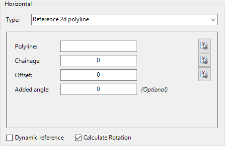
Reference 2D Polyline
|
|
Finds the midpoint between two codes on a String (such as the centreline and left edge of road) for the position
|
|
Polyline
|
Use the Pick icon to select a polyline from the drawing. The polyline 'handle' will be displayed once selected. |
| Chainage (Station) |
Type in a value or use the Pick icon to select in the drawing. |
| Offset |
Type in a value or use the Pick icon to select in the drawing. |
| Added angle |
Orientation will be taken from the polyline if 'Calculate Rotation' is ticked on. This adds an angle, in degrees, to the item |
|
|
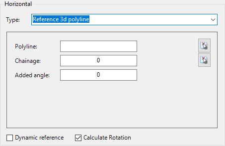
Reference 3D Polyline
|
|
Positions a point along a 3D polyline.
|
|
Polyline
|
Use the Pick icon to select a polyline from the drawing. The polyline 'handle' will be displayed once selected. |
| Chainage (Station) |
Type in a value or use the Pick icon to select in the drawing. |
| Added angle |
Orientation will be taken from the polyline if 'Calculate Rotation' is ticked on. This adds an angle, in degrees, to the item |
|
|
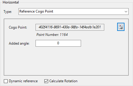
Reference COGO Point
|
|
Matches the insertion point of a COGO Point
|
|
Cogo Point
|
Use the pick button to select a COGO point from the drawing. The unique ID and point number will be displayed |
| Added Angle |
Type in a rotation relative to the Block Rotation on the reference COGO Point |
|
|
Dynamic Reference
|
Tick on to update horizontal position when the source reference item changes |
|
Calculate Rotation
|
Tick on to apply rotation based on the selected reference item (alignment, string, code) |
|
Vertical
|
Set up the vertical positioning of the object |
|
Type
|
Sets the method for setting up the elevation of the object. Options include: |
|
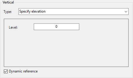
Specify Elevation
|
|
Type in an elevation
|
|
Level
|
Type in an elevation for the item
|
|
|
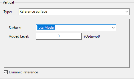
Reference Surface
|
|
Use a surface for elevations
|
|
Surface
|
Select a surface using the picklist |
| Added Level |
Type in a value above or below the selected surface |
| |
|
|
|
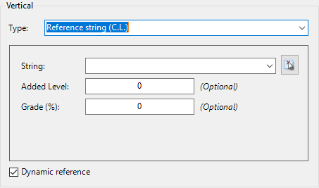
Reference String (C.L.)
|
|
Uses the design elevations at the centreline of a selected string
|
|
String
|
Select the string or use the pick item to select from the drawing |
| Added Level |
Type in a value above or below the selected string |
| Grade (%) |
Type in a grade (%) to apply from the reference string, , measured perpendicular to the string direction |
| |
|
|
|
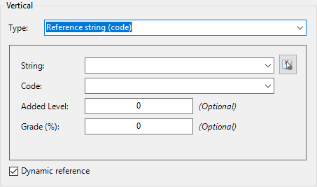
Reference String (Code)
|
Select the Code of a String for the elevation.
|
|
|
String
|
Select the design string or use the pick button to select from the drawing. |
| Code |
Select the design code for the elevations |
| Added Level |
Type in a value above or below the selected string code |
| Grade (%) |
Type in a grade to apply, measured perpendicular to the string direction |
| |
|
|
|
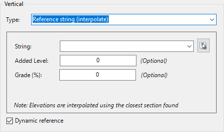
Reference String (interpolate)
|
This method uses the Horizontal Position and finds the nearest sampled design cross section of the selected String for elevations. Elevations are calculated at the offset determined by the Horizontal Position.
|
|
| String |
Select the design string or use the pick button to select from the drawing. |
| Added Level |
Type in a value above or below the selected string |
| Grade (%) |
Type in a grade to apply from the interpolated section location |
| |
|
|
|
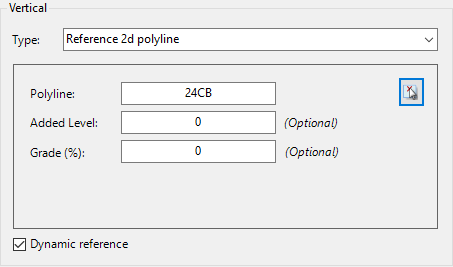
Reference 2D polyline
|
Select a 2D polyline in the drawing to reference for elevations. The single elevation assigned to the polyline will be used for elevation referencing.
|
|
| Polyline |
Use the Pick icon to select a polyline from the drawing. The polyline 'handle' will be displayed once selected. |
| Added Level |
Type in a value above or below the selected polyline |
| Grade (%) |
Type in a grade to apply, measured perpendicular to the polyline |
| |
|
|
|
Reference 3D Polyline
|
Select a 3D Polyline to reference for elevations
|

|
| Polyline |
Use the Pick icon to select a 3D polyline from the drawing. The polyline 'handle' will be displayed once selected. |
| Added Level |
Type in a value above or below the calculated elevation on the selected polyline (location measured perpendicular to the selected object) |
| Grade (%) |
Type in a grade to apply, measured perpendicular to the polyline |
| |
|
|
|
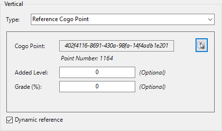
Reference COGO Point
|
Use a COGO Point as a reference for elevations
|
|
| Cogo Point |
Use the pick icon to select a COGO point from the drawing. The unique ID and the Point number will be displayed. |
| Added Level |
Type in a value above or below the selected COGO Point |
| Grade (%) |
Type in a grade to apply from the COGO Point |
| |
|
|
|
Dynamic Reference
|
Tick on to update vertical position when the source reference object changes |
|
OK
|
Apply and exit.
|
|
Cancel
|
Exit the form without deleting any data.
|