Viewer Settings
Icon:
![]()
Ribbon: Model Viewer > Home Tab > Settings Panel > Viewer Settings
Introduction
Settings for Model Viewer can be managed by the user via the Viewer Settings command. These settings include customisation of the Model Viewer interface and assignment of default styles for when Model Viewer is first used on a project.
Ribbon Tab and Navigation
This command forms part of the following tab:
![]()
Information on navigation in the Model Viewer 3D environment is available when reviewing the Model Viewer command help.
Details
Upon selecting the command the following form is displayed:
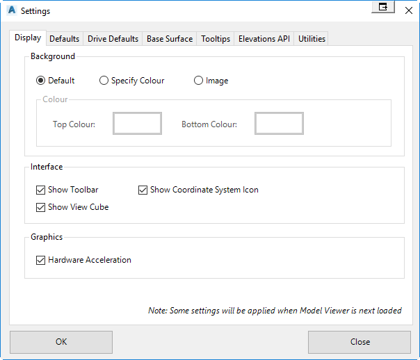
Display Tab
|
|
|
|
Background |
Users can customise the Model Viewer background by defining colours or an image from file. |
| Default | Sets the Model Viewer background to utilise the default style |
| Specify Colour | Allows the user to specify a top colour and a bottom colour to create a gradient for the background |
| Image | Users can specify an image loaded from file for the background. |
|
Interface |
Allows user to toggle on/off some of the display tools in Model Viewer |
| Show Toolbar | Users can toggle on/off the Model Viewer toolbar. This toolbar includes commands to zoom and pan around the model. |
| Show View Cube | Users can toggle on/off the Model Viewer view cube. The view cube is a handy tool allowing the user to quickly navigate to different views in the model |
| Show Coordinate Icon | Users can toggle on/off the Model Viewer coordinate icon. The coordinate icon is shown at the bottom-right corner of Model Viewer and displays the x,y, and z axis. |
|
Graphics |
|
| Hardware Acceleration | Turning on hardware acceleration will force Model Viewer to use the graphics card for processing of the 3d data. This can improve the performance of Model Viewer when used by certain modern graphics cards. |
|
OK |
Apply and exit. |
|
Cancel |
Exit the form |
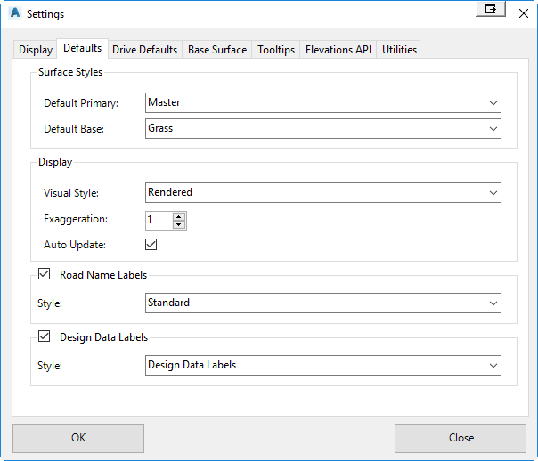
Defaults Tab
|
|
|
|
Surface Styles |
When a Model Viewer is first used on a project, the Toggle Display form will show. The default styles set in this form can be specified by the user here. |
| Default Primary | Allows the user to specify the default style for the Primary Surface. All available design styles are listed here. |
| Default Base | Allows the user to specify the default style for the Base Surface. All material groups are listed here. |
|
DIsplay |
Allows user to customise the default display options for when Model Viewer is first displayed. |
| Visual Style | Users can specify the default visual style. |
| Exaggeration | Users can specify the default exaggeration value. |
| Auto Update | Users can toggle on/off the auto update option. |
|
Road Name Labels |
Specify whether labels showing the road names will appear in Model Viewer on first load |
| Style | Specify the default label style for road name labels. |
|
Design Data Labels |
Specify whether labels showing the design data for main road will appear in Model Viewer on first load |
| Style | Specify the default label style for design data labels. |
|
OK |
Apply and exit. |
|
Cancel |
Exit the form |
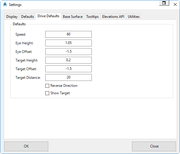
Drive Defaults Tab
|
|
|
|
Defaults |
|
| Speed | Sets the default speed value when the Drive command is used |
| Eye Height | Sets the default eye height value when the Drive command is used |
| Eye Offset | Sets the default eye offset value when the Drive command is used |
| Target Height | Sets the default target height value when the Drive command is used |
| Target Offset | Sets the default target offset value when the Drive command is used |
| Target Distance | Sets the default target distance value when the Drive command is used |
| Reverse Direction | Sets whether the Drive command will default to driving from the reverse end of the alignment |
| Show Target | Sets whether a yellow sphere is displayed at the target height and target offset when the Drive command is used |
|
OK |
Apply and exit. |
|
Cancel |
Exit the form |
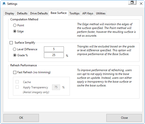
Base Surface Tab
|
|
|
|
Computation Method |
|
| Point | Using this method, the Base Surface is formed by re-triangulating the points that make up the surface specified. This method is faster, however less accurate as the edges of the surface specified are not always honoured. |
| Edge | Using this method, the Base Surface is created using the edges of the surface specified. This Base Surface formed is an accurate representation of the surface specified. |
|
Surface Simplify |
Toggle on/off surface simplification. This option will improve performance when displaying large surface data in Model Viewer. |
| Level Difference | Triangles are removed from the Base Surface using a level difference method. |
| Grade | Triangles are removed from the Base Surface using a grade difference method. |
| Fast Refresh | The slowest part of running a refresh in Model Viewer is the re-calculation of the base surface when it is required to trim the triangulation. Users have the option to toggle off the trimming of the base surface to considerably increase the performance of Model Viewer refreshing. This option is recommended when working with really large terrain data or if only minor changes are expected to be made to the the surface models on refresh. |
| Cache | When the software first calculates the base surface (inclusive of trimming), the software will record this information to memory. So on each refresh to the model. the cached base surface is used rather than a re-calculated base surface. This is recommended when working with large detailed surface data or when the job is almost complete and the user is simply working in Model Viewer to perform sight distance checks, import 3d models, or when it is not required to completely re-calculate the base surface. |
| Apply Transparency | This option will turn off trimming of the base surface completely. The base surface will then be displayed with a transparency, so the user can still see design data that exists below the base surface. |
|
OK |
Apply and exit. |
|
Cancel |
Exit the form |
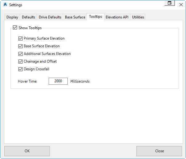
Tooltips Tab
|
|
|
|
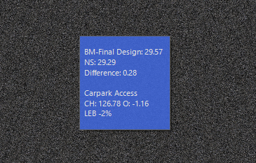
Show Tooltips |
Toggle on/off the display of tooltips in Model Viewer. All very large projects with plenty of road objects, users can increase performance of the tooltip by toggling off some of the items listed below. |
| Primary Surface Elevation | Toggle on/off the display of the primary surface elevation set in the toggle display command. |
| Base Surface Elevation | Toggle on/off the display of the base surface elevation set in the toggle display command. |
| Additional Surfaces Elevation | Toggle on/off the display of elevations for additional surfaces set in the toggle display command. |
| Chainage and Offset | Toggles on/off the display of chainage & offset information for the nearest road object. |
| Design Crossfall | Toggles on/off the display of code crossfall information for the nearest road object. |
| Hover Time | Sets the hover time of the mouse before the tooltip is displayed. |
|
OK |
Apply and exit. |
|
Cancel |
Exit the form |
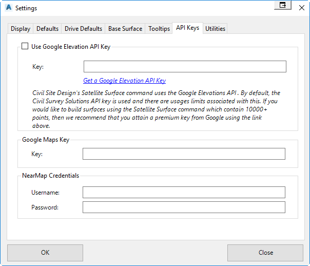
API Keys Tab
|
|
|
|
Use Google Elevation API Key |
The satellite from surface command uses the Google Elevations API to attain elevation data. By default, there is a limit of 10,000 points per surface when using this command. However, by specifying your own Google Elevations API key, you can turn off this point limit. A Google Elevations API key can be attained here. |
| Key | Specify your Google Elevations API Key to turn off the point limit of 10,000 points per surface. |
|
Google Maps Key |
If you have a Google Maps Key, then you can specify it for when accessing aerial imagery in Model Viewer. This is required for users who exceed for than 25,000 map loads per 24 hours. |
| Key | Specify your Google Maps API Key. |
|
NearMap Credentials |
When importing aerial imagery into Model Viewer, users have the option to reference NearMap data if they have a valid account. In order to reference NearMap data, it will be required to specify your username and password information. |
| Username | Specify your NearMap account username. |
| Password | Specify your NearMap account password. |
|
OK |
Apply and exit. |
|
Cancel |
Exit the form |
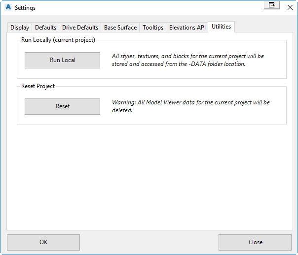
Utilities Tab
|
|
|
|
Run Local |
Allows the user to run Model Viewer from the -DATA folder. All styles, textures, and 3d models will be stored in the -DATA folder location. This command should be used when sending data to another Civil Site Design user or when sending the project to the technical support system. |
|
Reset |
If Model Viewer data has become corrupted, than this command will delete all Model Viewer related data for the current project allowing the user to restart. |
|
OK |
Apply and exit. |
|
Cancel |
Exit the form |