Toggle Display
Icon:
![]()
Ribbon: Model Viewer > Home Tab > View Panel > Toggle Display
Introduction
The Toggle Display command allows users to manage the display of surfaces and system labels in Model Viewer. The Toggle Display dialog will load when you first run the Model Viewer command on a project. The default styles assigned to the Primary Surface, Base Surface, and system labels can be setup in the Viewer Settings.
This command is very much associated with the Refresh command, because the Refresh command will update the display of data as setup in the Toggle Display dialog. If there are issues with the display of information in Model Viewer, than it recommend that you first review the Toggle Display setup.
In Model Viewer, users can specify a Primary Surface and a Base Surface. The Primary Surface is the main design surface and commands such as Assign Materials to Triangle will reference only the Primary Surface.
The Base Surface is generally set as your existing terrain surface. Users have the ability to drape aerial imagery over the Base Surface and parts of the Base Surface can be trimmed out where design surfaces exist. The Trim Base (surface) is used when it required to trim the Base Surface out using the extents of the specified design surface.
Ribbon Tab and Navigation
This command forms part of the following tab:
![]()
Information on navigation in the Model Viewer 3D environment is available when reviewing the Model Viewer command help.
Details
Upon selecting the command the following form is displayed:
Surfaces Tab
|
|
|
| File | |
| Save Display | Users have the option to save parameters set in the Toggle Display form. The is useful for users who have a long list of surface models and want to save and reload different display states. |
| Open Display | Users have the option to open saved parameters in the 'Toggle Display' form. The is useful for users who have a long list of surface models and want to save and reload different display states. It is recommended that if the Combined Surface command is used, then the user should save this display so that the display can be re-loaded if an update to the combined surface is required. |
|
Primary Design |
Set as the main design surface displayed in Model Viewer. The display of this surface can be toggled on/off. Commands such as Assign Materials to Triangle will only reference this surface. |
|
Name |
All design surfaces are listed here. Only surfaces created using commands such as Auto Model, Model Builder, Grading will be listed. The Trim Base (surface) is used when it required to trim the Base Surface out using the extents of the specified design surface. |
| Style |
All design surface styles are listed. Users can create/edit
a design style
if required, by selecting
|
|
Base Surface |
The Base Surface is generally set as your existing terrain surface. Users have the ability to drape aerial imagery over the Base Surface and parts of the Base Surface can be trimmed out where design surfaces exist. The Trim Base (surface) is used when it required to trim the Base Surface out using the extents of the specified design surface. The display of this surface can be toggled on/off. |
| Name | All non-design surfaces are listed here. These are surfaces such as AutoCAD Civil3D surfaces or surfaces created using Civil Site Design's Create/Edit Surface command. |
| Style | Users have the option to either drape an aerial image over this surface or assign a material group. If the user selects Image from Drawing (Aerial Photo), a dialog will display with an option to select an image from the drawing. Model Viewer will reference the image directly from its file path. The position and scale of the image will reflect the position and scale of the image in the drawing. |
|
Additional Surfaces |
All other surfaces in the project are listed here. Users have the option to toggle on/off the visibility of these surfaces and set whether they will trim out the Base Surface. These surfaces can be styled by assigning a material group. Selecting the button '...' will open the material groups dialog. |
|
OK |
Apply and exit. |

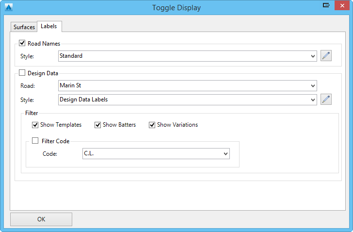
Labels Tab
|
|
|
|
Road Names |
On each road, a label displaying the road name can be shown. This label can be toggled on/off. |
| Style |
All label
styles are listed here and the user can select the
style used for the display of the road label. The label
style can be edited by pressing
|
|
Design Data |
For a specified road, the design data (from the Design Data Form) is displayed. Within Model Viewer, users can see templates assigned to a road, variations applied, along with other edits. These labels can be toggles on/off. |
| Name | Select the road to display design data labels for. |
| Style |
All label
styles are listed here and the user can select the
style used for the display of the design data labels. The
label style can be edited by pressing
|
|
Filter & Code Filter |
Rather than showing all design data information, users can toggle on/off the display of items such as templates, batters, or variations. Also, the user has the ability to filter the design data for a single design code (i.e. the LEB code). For example, this option would allow the user to see only variations that have been applied to the LEB code. |
|
OK |
Apply and exit. |
Click here for information regarding importing Point Clouds into Model Viewer.
Contours Tab
|
|
|
|
Surface Name |
Lists all surfaces in the current project. In order to see the contours displayed, contours for the surface must be currently displayed in plan. |
| Lineweight | Allows the user to specify the lineweight of the contours to be displayed. Colour of the contours will be the same as the contours currently displayed in plan. |

Note: At this stage, contours for Civil3D Surfaces cannot be displayed in Model Viewer. If you would like to display contours for a Civil 3D Surface, then it is recommended to convert the Civil 3D to a Civil Site Design Surface by using the Combined Surface command.