Model Viewer
Icon:
![]()
![]()
Menu: Roads > Select/Open/Edit > Model Viewer
General > Model Viewer
Grading > Model Viewer
Surfaces > Model Viewer (AutoCAD and BricsCAD only)
Ribbon: Roads Tab > Select Panel > Model Viewer
Grading Tab > 3D View Panel > Model Viewer
General Tab > 3D View Panel > Model Viewer
Surfaces Tab > 3D View Panel > Model Viewer (AutoCAD and BricsCAD
only)
Introduction
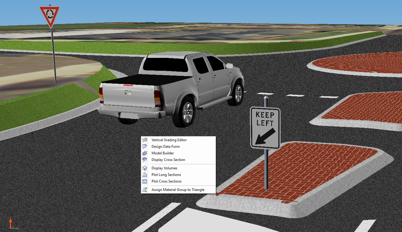
Model Viewer provides a spatially accurate, fully rendered, model of your surfaces and designs, updating as you make design changes and including analysis for sight distance. This is a full 3D environment with zoom, pan and orbit navigation. Any alignment can be immediately driven to assess visual and design outcomes. Sight distance analysis accounts for all surfaces, design features and objects in assessing whether adequate sight distance is provided for each road and intersection.
Video Help on Model Viewer

A video playlist on the use of Model Viewer is available here.
Mouse controls are used to navigate in the environment.
The Model Viewer is made up of three primary components:
-
A tabbed ribbon interface at the top of the form, containing commands to manage the display of items and to generate analysis and reports
-
A 3D view area displaying the models in the middle of the form
-
A progress bar and command information text at the bottom of the form
At the bottom left corner is a UCS icon, showing the orientation of the model. This is not editable.
Ribbon Interface Controls
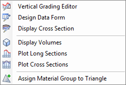
The Ribbon is divided into a number of Tabs, grouped by functionality. For individual command help, please expand the relevant command using the Help navigation pane on the left. Ribbon tabs include:
- Home Tab: this tab manages the overall display of the environment and setting up how models should be displayed
- Analysis Tab: this tab provides access to model analysis including drive animations and sight distance calculations
- Objects Tab: this tab facilitates inclusion of 3D objects in the display
- Labels Tab: this tab enables the addition of labels in the drawing to describe design objects
- Outputs Tab: this tab manages outputs including screen shots and videos.
3D Model Navigation and Selection Controls
You can zoom, pan and orbit around the 3D environment, as well as execute commands to edit/review/analyse objects in the model.
Note: There are some specific selection techniques when particular commands are invoked, such as Select Objects. The mouse actions will be outlined for each command where it differs from the below default navigation behaviour.
Below is a description of the methods for navigating and selecting objects. The model environment includes a number of navigation controls which are outlined below:
|
Navigation Modes |
Sets different methods for navigation | ||||||||||||||||||||||||||
|
Default Navigation Mode |
By default, Pan mode is
normally enabled, with the following controls:
|
||||||||||||||||||||||||||
|
|
These navigation modes change what the Left Mouse selection will do | ||||||||||||||||||||||||||
|
Zoom Window |
Drag the left mouse button to form a window to zoom to | ||||||||||||||||||||||||||
| Zoom | Hold down and move the left mouse button to dynamically zoom in and out | ||||||||||||||||||||||||||
|
Pan |
Hold down and move the left mouse button to move left/right/up/down | ||||||||||||||||||||||||||
|
Orbit |
Hold down and move the left mouse button to orbit about the cursor position (set at the time of commencing the orbit) | ||||||||||||||||||||||||||
|
Zoom Fit |
Zooms to show the entire model | ||||||||||||||||||||||||||
|
|
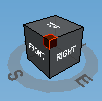
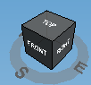
The View Cube facilitates rotation/orbit of the model via
direct manipulation of the cube in the display. Holding down the left mouse button over the cube will enable orbiting of the model. Hovering on the cube will highlight different 'parts' of the cube. Left click selection will change the view based on the 'part' highlighted. Samples below |
||||||||||||||||||||||||||
|
|
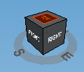
When a face of the cube is highlighted, clicking on that
face will zoom to it. In the example, left, clicking on the Top will show a top view of the model, oriented North. This is the Home (starting) orientation |
||||||||||||||||||||||||||
 |
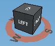
When a corner is highlighted, clicking on that corner will
zoom to an isometric view. Clicking on a 'side' will set to that side. |
||||||||||||||||||||||||||
|
|
When the 'compass' is highlighted, holding down the left
mouse will constrain the orbit to a horizontal rotation,
while maintaining the vertical rotation angle. Click on N, S, E, W to go to a front view at that orientation |
||||||||||||||||||||||||||
Shortcut Keys
|
Shortcut Key |
Command |
| CTRL + R | Refresh Model Viewer |
| CTRL + C | Create a copy of the selected Object |
| CTRL + T | Toggle the display of tooltips - the display of tooltips are managed in the Viewer Settings |
| DELETE | Delete the selected Object |