Active Network Settings
| Icon: | |
| Menu: | CSD Pipes > Settings > Active Network Settings |
| Ribbon: | Pipes Tab > Settings Panel > Active Network |
Introduction
The CSD Pipes module of Civil Site Design software requires the Designer to setup what pipes & pits are available, how they want the software to perform and how objects are displayed for a specific drawing (or project).
The Active Network Settings form includes multiple tabs for control over the following functionality and object display:
- Pipe, Box Section, Service Obstruction and Pit tables including geometric and hydraulic properties;
- Object layer & labelling display controls;
- Object snapping tolerances settings;
- Drainage rainfall table definition (IDF & Log co-efficient);
- Sewer design tables and House Connection definition;
The Active Network Settings is used to control the settings for the current drawing only, also referred to as Local Settings.
The initial settings for this form are populated from the selected Global Network Settings when a project is first started. The Global Network Settings command is used to edit a Global Network Settings file.
Details
Upon selecting the command the following form is displayed:
 The Active Network Settings is broken up into several main tabs: (Click on a tab for more information about that tab):
|
|
| OK | Apply and exit. |
| Cancel | Exit the form without deleting any data. |


General Tab
The General tab is used to configure project settings common to all network types (Drainage, Sewer and Services Obstructions). It is divided up into the following tabs (Click on a tab for more information about that tab):

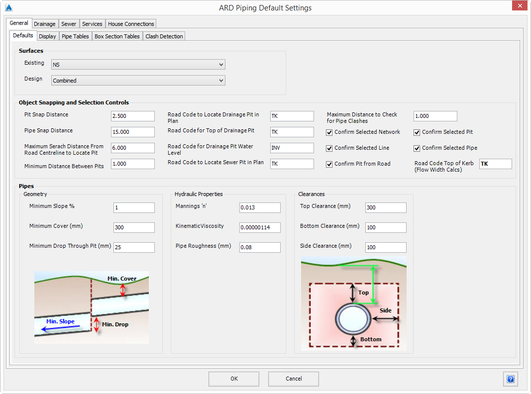
Defaults Tab
The General - Defaults tab is used to configure the surfaces, object snapping and pipe default geometric, hydraulic and clearance properties.
Note: To adjust the focus to show information about a different tab, just click on the tab of interest.
 |
|
| Surfaces | Select the surface (terrain) models that are used as the Existing and Design surfaces for the project. |
| Existing | Select the surface to be used as the Existing surface. |
| Design | Select the surface to be used as the Design surface. The surface must exist for all pit and pipe locations. The Design Surface is used for calculating pipe cover and is the default surface used for locating the top of pits. |
| Object Snapping and Selection Controls | Set the object snapping options for Pit & Pipe creation and editing. |
| Pit Snap Distance | Set the distance (in drawing units) to snap when selecting a pit. |
| Pipe Snap Distance | Set the distance (in drawing units) to snap when selecting a pipe. |
| Maximum Search Distance From Road Centreline to Locate Pit | Set the maximum distance (in drawing units) from any Road centreline the software will search for when locating a pit. When a pit is being created and a location is specified within the search distance to a road, the user will be given the option to associate it to the Road. |
| Minimum Distance Between Pits | Set the minimum distance (in drawing units) between pits. If the minimum distance is violated when locating a pit the user will be prompted with a warning message. |
| Road Code to Locate Drainage Pit in Plan | Specify the default Road Code to locate a drainage pit. The code must be entered without the L or R prefix. |
| Road Code for Top of Drainage Pit | Specify the default Road Code the top of a drainage pit is associated with. The code must be entered without the L or R prefix. |
| Road Code for Drainage Pit Water Level | Specify the default Road Code the hydraulic design level of a drainage pit is associated with. The code must be entered without the L or R prefix. |
| Road Code to Locate Sewer Pit in Plan | Specify the default Road Code to locate a sewer pit. The code must be entered without the L or R prefix. |
| Maximum Distance to Check for Pipe Clashes | Specify the maximum distance (in drawing units) to check for pipe clashes. The network type to be included in clash detection are set on the Clash Detection tab. |
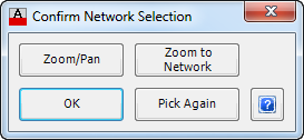
| Confirm Selected Network | Enables or disables the Confirm Network when selecting a network.
|
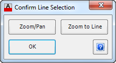
| Confirm Selected Line | Enables or disables the Confirm Line (or Branch) when selecting a line/branch of a network.
|
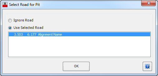
| Confirm Pit from Road | Enables or disables the Confirm Pit from Road when creating pit associated with a road.
Note: In the Road List, offset is distance first, followed by the Chainage, then the Alignment Name. |
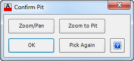
| Confirm Selected Pit | Enables or disables the Confirm Pit form when selecting a pit.
|
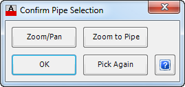
| Confirm Selected Pipe | Enables or disables the Confirm Pipe form when selecting a pipe.
|
| Road Code Top of Kerb (Flow Width Calcs) | In order to determine the road extents within which to calculate the water depths at pits, users need to specify a Code from the Road cross sections that represents the outside edge for depth calculations. Normally this would be the top of kerb (TK) or back of kerb. Users can set this code themselves here. |
| Pipes | Define the overall properties for the all the Pipes (including Box Sections) if no other values are defined for the class default or object itself. |
| Geometry | Define the overall geometry properties. |
| Minimum Slope % | Set the minimum slope as a percentage. |
| Minimum Cover (mm) | Set the minimum cover in millimetres. |
| Minimum Drop Through Pit (mm) | Set the minimum drop through the pit in millimetres. |
| Hydraulic Properties | Define the overall hydraulic properties. |
| Mannings 'n' | Set the Mannings 'n' number. |
| Kinematic Viscosity | Set the Kinematic Viscosity value. |
| Pipe Roughness (mm) | Set the Pipe Roughness value in millimetres. |
| Clearances | Define the overall clearances. |
| Top Clearance (mm) | Set the top clearance from the outside of the pipe in millimetres. |
| Bottom Clearance (mm) | Set the bottom clearance from the outside of the pipe in millimetres. |
| Side Clearance (mm) | Set the side clearance from the outside of the pipe in millimetres. |
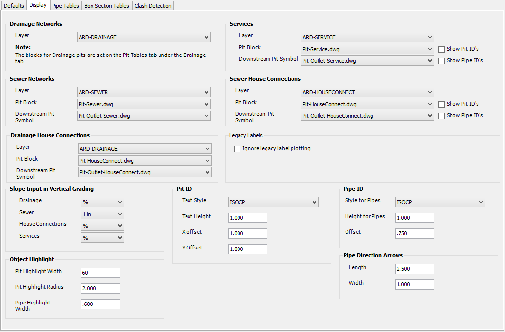
Display Tab
The General - Display tab is used to configure the display of the various pipe networks & labelling and also the object highlight settings.
Note: To adjust the focus to show information about a different tab, just click on the tab of interest.
 |
|
| Drainage Networks | Configure the display controls for Drainage Networks. |
| Layer | Select the layer used to display drainage networks (pits, pipes, direction arrows and pipe labels). The pit labels are displayed on a layer the same as selected with the same name plus the suffix -Text. Use the Edit Layer Settings command to edit the layers available. The Ignore Legacy Label Plotting toggle will stop these labels from being drawn. |
| Services | Configure the display controls for Service Obstruction Networks. |
| Layer | Select the layer used to display service obstruction networks (pits, pipes, direction arrows and pipe labels). Use the Edit Layer Settings command to edit the layers available. |
| Pit Block | Select the block used to represent the service obstruction pits in the drawing. The block is aligned to the downstream pipe when the service obstruction is created. The blocks are initially loaded from the CSD common folder and then from the drawing. |
| Downstream Pit Symbol | Select the block used to represent the downstream service obstruction pit for each network. The block is aligned to the downstream pipe when the service obstruction is created. The blocks are initially loaded from the CSD common folder and then from the drawing. |
| Show Pit ID's | Tick box to enable or disable the display of the pit labels for service obstruction pits. |
| Show Pipe ID's | Tick box to enable or disable the display of the pipe labels for service obstruction pits. |
| Sewer Networks | Configure the display controls for Sewer Networks. |
| Layer | Select the layer used to display sewer networks (pits, pipes, direction arrows and pipe labels). The pit labels are displayed on a layer the same as selected with the same name plus the suffix -Text. Use theEdit Layer Settings command to edit the layers available. The Ignore Legacy Label Plotting toggle will stop these labels from being drawn. |
| Pit Block | Select the block used to represent the sewer pits in the drawing. The block is aligned to the downstream pipe when the sewer network is defined. The blocks are initially loaded from the CSD common folder and then from the drawing. |
| Downstream Pit Symbol | Select the block used to represent the downstream sewer pit for each network. The block is aligned to the downstream pipe when the sewer network is defined. The blocks are initially loaded from the CSD common folder and then from the drawing. |
| Sewer House Connections | Configure the display controls for Sewer House Connection Networks. |
| Layer | Select the layer used to display sewer house connection networks (pits, pipes, direction arrows and pipe labels). Use the Edit Layer Settings command to edit the layers available. |
| Pit Block | Select the block used to represent the sewer house connection pits in the drawing. The block is aligned to the downstream pipe when the sewer house connection is created. The blocks are initially loaded from the CSD common folder and then from the drawing. |
| Downstream Pit Symbol | Select the block used to represent the downstream sewer house connection pit for each network. The block is aligned to the downstream pipe when the sewer house connection is created. The blocks are initially loaded from the CSD common folder and then from the drawing. |
| Show Pit ID's | Tick box to enable or disable the display of the pit labels for sewer house connection pits. |
| Show Pipe ID's | Tick box to enable or disable the display of the pipe labels for sewer house connection pits. |
| Drainage House Connections | Configure the display controls for Drainage House Connection Networks. |
| Layer | Select the layer used to display drainage house connection networks (pits, pipes, direction arrows and pipe labels). Use the Edit Layer Settings command to edit the layers available. |
| Pit Block | Select the block used to represent the drainage house connection pits in the drawing. The block is aligned to the downstream pipe when the drainage house connection is created. The blocks are initially loaded from the CSD common folder and then from the drawing. |
| Downstream Pit Symbol | Select the block used to represent the downstream drainage house connection pit for each network. The block is aligned to the downstream pipe when the drainage house connection is created. The blocks are initially loaded from the CSD common folder and then from the drawing. |
| Legacy labels | Legacy labels are the automatic pit and pipe labels that are displayed when pipes and pits are created. Initially, pit labels display automated numbers, replaced by Pit ID's or following branch sequencing and assignment of a pit naming convention. |
| Ignore Legacy label plotting | Traditionally, pit and pipe labels were automatically drawn as pipes and pits were created, for drainage and sewer networks. Since Civil Site Design V16 new labelling tools are available, enhancing the drafting control of text, symbols and linework associated with the labels. The Network Labels command can be used for this newer labelling - if this is planned, then the older (duplicate) labelling is probably not required. |
| Slope Input in Vertical Grading | Users are able to set, on a network-by-network basis, whether to use percentage grades (%) or slopes (rise:run) to design the pipes in the Vertical Grading Editor. Inputs inside the Vertical Grading Editor will be adjusted to match this selection. |
| Drainage | Select to design using slopes (%) or grades (1 in) when editing a Drainage network using the Vertical Grading Editor. |
| Sewer | Select to design using slopes (%) or grades (1 in) when editing a Sewer network using the Vertical Grading Editor. |
| House Connections | Select to design using slopes (%) or grades (1 in) when editing a House Connection using the Vertical Grading Editor |
| Services | Select to design using slopes (%) or grades (1 in) when editing a Service Obstruction using the Vertical Grading Editor. |
| Object Highlight | Configure the Object Highlight controls for all pipes and pits. Selected objects are highlighted by the software to clearly identify a user selection. The current layer is used for the highlight object. |
| Pit Highlight Width | Enter the width of the outer circle of the pit crosshair highlight in millimetres x 100. A crosshair is drawn to indicate the pit selected when the Pit Confirmations are turned on. The pit highlight width is only shown when the Lineweight is enabled in the drawing. |
| Pit Highlight Radius | Enter the radius of the pit highlight in drawing units. |
| Pipe Highlight Width | Enter the width of the line used to highlight a pipe in drawing units. The pipe is highlighted only when the Pipe Confirmations are turned on. |
| Pit ID | Configure the display of Pit labels. The Pit labels can be moved in the drawing and the offsets to the Pit location is maintained by the software. The label can be reset be simply deleting it and refreshing the network display using theRedraw Networks command. A default circle will be displayed around the Pit label. |
| Text Style | Select the text style to be used. |
| Text Height | Enter the text height in drawing units. |
| X offset | Enter the default X offset from the pit insertion point to draw the pit label. |
| Y offset | Enter the default Y offset from the pit insertion point to draw the pit label. |
| Pipe ID | Configure the display of the Pipe labels. Pipe labels are oriented parallel to the pipe. |
| Style for Pipes | Select the text style to be used. |
| Height for Pipes | Enter the text height in drawing units. |
| Offset | Enter the offset from the Pipe centreline for the Pipe label location. |
| Pipe Direction Arrows | Configure the display of the Pipe Direction Arrows. The arrows are only drawn when the pipe and pits are defined as a network. |
| Length | Enter the length in drawing units. |
| Width | Enter the width in drawings units. |
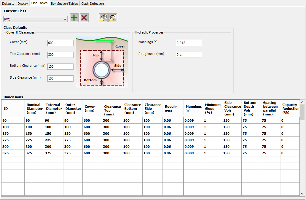
Pipe Tables Tab
The General - Pipe Tables tab is used to configure the various pipe classes and types available in the project.
Note: To adjust the focus to show information about a different tab, just click on the tab of interest.
 |
|
| Current Class | Select the pipe class to be viewed/edited. |
 New Class New Class |
Create a new pipe class. |
 Delete Current Class Delete Current Class |
Delete the current pipe class. Note: The 'Default' pipe class can not be deleted. |
 Export Current Class Export Current Class |
Export the current pipe class to file. See Importing & Exporting Tables below. |
 Import Class Import Class |
Import a pipe class from file. See Importing & Exporting Tables below. |
| Class Defaults | Set the class defaults. |
| Cover & Clearances | Set the cover and clearances. |
| Cover (mm) | Set the minimum cover in millimetres. |
| Top Clearance (mm) | Set the top clearance from the outside of the pipe in millimetres. |
| Bottom Clearance (mm) | Set the bottom clearance from the outside of the pipe in millimetres. |
| Side Clearance (mm) | Set the side clearance from the outside of the pipe in millimetres. |
| Hydraulic Properties | Set the hydraulic properties. |
| Mannings 'n' | Set the Mannings 'n' number. |
| Roughness (mm) | Set the pipe Roughness value in millimetres. |
| Dimensions | Set the pipe properties for each pipe type in the class. It is recommended that all values are set for each pipe type. |
| ID | Enter the ID (identifier) for the pipe. |
| Nominal Diameter (mm) | Enter the nominal diameter for the pipe in millimetres. |
| Internal Diameter (mm) | Enter the internal diameter for the pipe in millimetres. |
| Outer Diameter (mm) | Enter the outer diameter for the pipe in millimetres. |
| Cover (mm) | Enter the cover for the pipe in millimetres. |
| Clearance Top (mm) | Enter the top clearance from the outside of the pipe in millimetres. |
| Clearance Bottom (mm) | Enter the bottom clearance from the outside of the pipe in millimetres. |
| Clearance Side (mm) | Enter the side clearance from the outside of the pipe in millimetres. |
| Roughness | Enter the pipe roughness value in millimetres. |
| Mannings 'n' | Enter the pipe Mannings 'n' number. |
| Minimum Slope (%) | Enter the minimum pipe slope as a percentage. |
| Side Clearance Vols (mm) | Enter the side clearance from the outside of the pipe in millimetres to be used for a Trench Volume Report. |
| Bottom Depth Vols (mm) | Enter the bottom clearance from the outside of the pipe in millimetres to be used for a Trench Volume Report. |
| Spacing between parallel (mm) | Enter the spacing between pipes (measured from the outside edges of the pipes) when multiple parallel pipes are specified to be used for a Trench Volume Report. |
| Capacity Reduction (%) | Users are able to set a percentage blockage factor (capacity reduction) per pipe. This value can be applied to the pipes in a Drainage network to show the reduction in Mannings and HGL flow capacity (litres/second) if the capacity reduction factor is applied. Zero implies no reduction. 100 implies total blockage. Note: Users must turn on the option to apply the capacity reduction factors from the Drainage - Design Settings tab. The display of the Hydraulic Grade Line (HGL) in the Vertical Grading Editor will not be affected by the reduction factors applied - designers need to review the reduced flow capacities and surcharges reported by the software. |
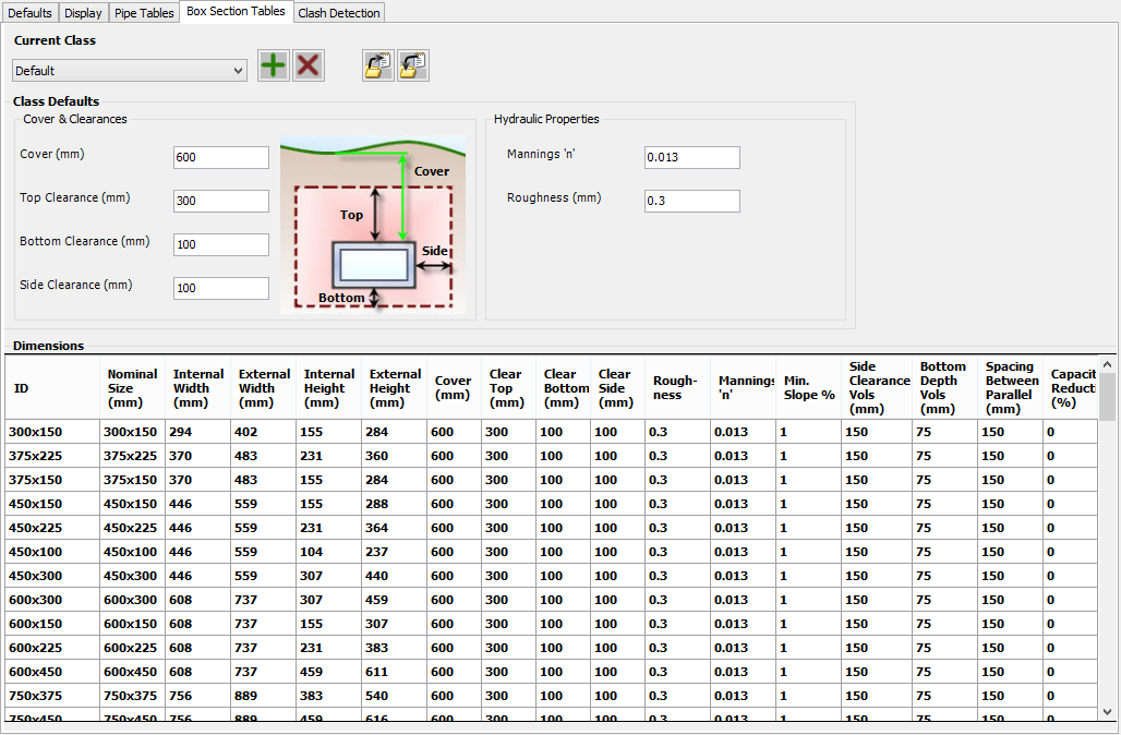
Box Section Tables Tab
The General - Box Section Tables tab is used to configure the various box sections classes and types available in the project.
Note: To adjust the focus to show information about a different tab, just click on the tab of interest.
 |
|
| Current Class | Select the box section class to be viewed/edited. |
| New Class |
Create a new box section class. |
| Delete Current Class |
Delete the current box section class. Note: The 'Default' box section class can not be deleted. |
| Export Current Class |
Export the current box section class to file. See Importing & Exporting Tables below. |
| Import Class |
Import a box section class from file. See Importing & Exporting Tables below. |
| Class Defaults | Set the class defaults. |
| Cover & Clearances | Set the cover and clearances. |
| Cover (mm) | Set the minimum cover in millimetres. |
| Top Clearance (mm) | Set the top clearance from the outside of the box section in millimetres. |
| Bottom Clearance (mm) | Set the bottom clearance from the outside of the box section in millimetres. |
| Side Clearance (mm) | Set the side clearance from the outside of the box section in millimetres. |
| Hydraulic Properties | Set the hydraulic properties. |
| Mannings 'n' | Set the Mannings 'n' number. |
| Roughness (mm) | Set the box section Roughness value in millimetres. |
| Dimensions | Set the box section properties for each box section type in the class. It is recommended that all values are set for each box section type. |
| ID | Enter the ID (identifier) for the box section. |
| Nominal Size (mm) | Enter the nominal size for the box section in millimetres. |
| Internal Width (mm) | Enter the internal width for the box section in millimetres. |
| External Width (mm) | Enter the external width for the box section in millimetres. |
| Internal Height (mm) | Enter the internal height for the box section in millimetres. |
| External Height (mm) | Enter the external height for the box section in millimetres. |
| Cover (mm) | Enter the cover for the box section in millimetres. |
| Clear Top (mm) | Enter the top clearance from the outside of the box section in millimetres. |
| Clear Bottom (mm) | Enter the bottom clearance from the outside of the box section in millimetres. |
| Clear Side (mm) | Enter the side clearance from the outside of the box section in millimetres. |
| Roughness | Enter the box section roughness value in millimetres. |
| Mannings 'n' | Enter the box section Mannings 'n' number. |
| Min Slope % | Enter the minimum box section slope as a percentage. |
| Side Clearance Vols (mm) | Enter the side clearance from the outside of the box section in millimetres to be used for a Trench Volume Report. |
| Bottom Depth Vols (mm) | Enter the bottom clearance from the outside of the box section in millimetres to be used for a Trench Volume Report. |
| Spacing Between Parallel (mm) | Enter the spacing between box sections (measured from the outside edges of the box sections) when multiple parallel box sections are specified to be used for a Trench Volume Report. |
| Capacity Reduction (%) | Users are able to set a percentage blockage factor (capacity reduction) per box section. This value can be applied to the box sections in a Drainage network to show the reduction in Mannings and HGL flow capacity (litres/second) if the capacity reduction factor is applied. Zero implies no reduction. 100 implies total blockage. Note: Users must turn on the option to apply the capacity reduction factors from the Drainage - Design Settings tab. The display of the Hydraulic Grade Line (HGL) in the Vertical Grading Editor will not be affected by the reduction factors applied - designers need to review the reduced flow capacities and surcharges reported by the software. |
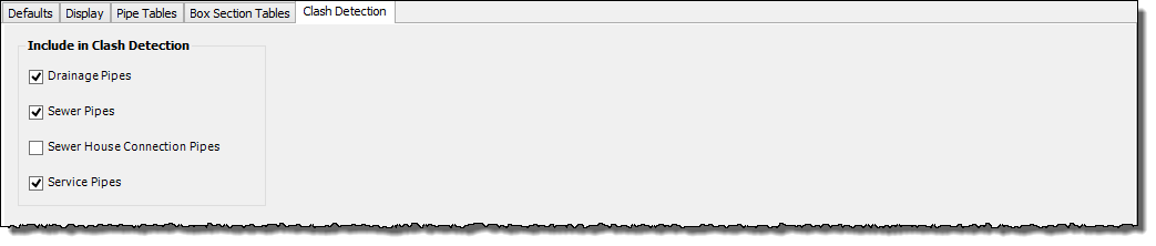
Clash Detection Tab
The General - Clash Detection tab is used to configure what type of networks are shown in theVertical Grading Editor and the Clash Detection Report as crossing objects.
Note: To adjust the focus to show information about a different tab, just click on the tab of interest.
 |
|
| Include in Clash Detection | Select the items to be shown in the VGE as crossing pipes and Clash Detection Report as crossing objects. |
| Drainage Pipes | Enable/disable drainage pipes. |
| Sewer Pipes | Enable/disable sewer pipes. |
| Sewer House Connection Pipes | Enable/disable sewer house connection pipes. |
| Service Pipes | Enable/disable service obstruction pipes. |
Drainage Tab
The Drainage tab is used to configure project settings specific to Drainage networks. It is divided up into the following tabs (Click on a tab for more information about that tab):

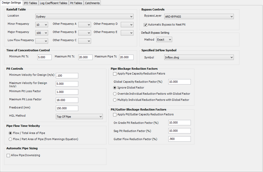
Design Settings Tab
The Drainage - Design Settings tab is used to configure the various design settings used for the analysis of drainage networks.
Note: To adjust the focus to show information about a different tab, just click on the tab of interest.
 |
|
| Rainfall Table | Define the rainfall location and frequencies to be used for the drainage analysis. |
| Location | Select the location to be used. Either a IFD or a Log Coefficient table can be selected. |
| Minor Frequency | Select the frequency to be used as the minor storm event. The pipes are sized and their invert levels established based on this setting. A value MUST be selected for the Minor Frequency. |
| Major Frequency | Select the frequency to be used as the major storm event. Leave blank if not required. |
| Low Flow Frequency | Select the frequency to be used as the low flow (GPT Design) event. Leave blank if not required. |
| Other Frequency A | Select the frequency to be used as the Other Frequency A event. Leave blank if not required. |
| Other Frequency B | Select the frequency to be used as the Other Frequency B event. Leave blank if not required. |
| Other Frequency C | Select the frequency to be used as the Other Frequency C event. Leave blank if not required. |
| Other Frequency D | Select the frequency to be used as the Other Frequency D event. Leave blank if not required. |
| Other Frequency E | Select the frequency to be used as the Other Frequency E event. Leave blank if not required. |
| Bypass Controls | Define the global bypass controls for drainage networks. |
| Bypass Layer | Select the layer used to display drainage bypass. Use the Edit Layer Settings command to edit the layers available. |
| Automatic Bypass to Next Pit | Tick box to Enable or Disable automatic bypass control to the next downstream pit. When a drainage network is defined (or re-defined) and this option is ON, then any pit without bypass control will automatically assign its bypass to the next downstream pit. |
| Default Bypass Setting | A setting to control the Method for Pipe Bypass to be treated. |
| Method | A drop box to select from one of three methods - Exact, Linear, Top Pit. New networks adopt this method for treating pit flows to the pipe. The Method can be edited on a network-by-network basis using the Bypass Method command. This command also includes an explanation of the different methods. For further details on the methods, click on this document link. |
| Linear Time Step | If the Linear Method is selected, then the user must enter a suitable time step. Flows will be pre-calculated and interpolated between the time step selected. Default value: 0.25 |
| Time of Concentration Control | Provides controls for the minimum and maximum times of concentration that are applied to pits and pipes. |
| Minimum Pit Tc | Specify the minimum time of concentration for runoff to a pit, in minutes. This will also apply to the outlet pipe, if applicable. |
| Maximum Pit Tc | Specify the maximum time of concentration for runoff to a pit, in minutes. |
| Maximum Pipe Tc | Specify the maximum time of concentration to be used for pipes, in minutes. |
| Specified InFlow Symbol | Users are able to specify direct inflows to a pit via the Pit Inflows command. A symbol can be drawn at the pit to indicate that a specified inflow has been applied. |
| Symbol | Select the block used to represent that a specified inflow has been applied to a pit. The block is inserted at the centre of the pit. The blocks are initially loaded from the CSD Common folder and then from the drawing. |
| Pit Controls | Define the pit controls used when creating/updating a drainage network. These controls are automatically applied to size the pipes and establish invert levels suitable for the Minor Frequency storm event. |
| Minimum Velocity for Design (m/s) | Specify the minimum velocity in metres per second. |
| Maximum Velocity for Design (m/s) | Specify the maximum velocity in metres per second. |
| Minimum Pit Loss Factor | Specify the minimum pit loss factor. |
| Maximum Pit Loss Factor | Specify the maximum pit loss factor. |
| Freeboard (mm) | Specify the freeboard at the pit in millimetres. |
| HGL Method | Select either Top of Pipe or Pipe Partial Water Level. Top of Pipe will make the HGL follows the top of the pipe. Pipe Partial Water Level will make the HGL follow the pipe partial water level. |
| Pipe Flow Time Velocity | The flow time calculated for a pipe can be defined by using either the total area of the pipe or the partial flow area. Users are able to select which calculation method to apply for determining the time of concentration (tc) throughout the network. Toggle the required option. |
| Flow/Total Area of Pipe | Calculates the flow time assuming the pipe is running full. |
| Flow/Part Area of Pipe from Mannings equation) | Calculates the flow time using the calculated area of water in the pipe. |
| Pipe Blockage Reduction Factors | Define whether pipe flows are to be calculated using a reduced pipe area. This is useful for a sensitivity check on the system performance in the event of a blockage in the network. Note: The display of the Hydraulic Grade Line (HGL) in the Vertical Grading Editor will not be affected by the reduction factors applied - designers need to review the reduced flow capacities and surcharges reported by the software. |
| Apply Pipe Capacity Reduction Factors | Tick box to Enable or Disable reduction factors in the calculation of pipe flow capacities. |
| Global Capacity Reduction Factor (%) | Specify a global reduction factor that may be applied to all pipes throughout the drainage network. Zero implies no blockage and 100 implies total blockage. |
| Ignore Global Factor | Toggle this option on to apply the reduction factors for each pipe as specified in the Pipe Tables and ignore any global reduction factors |
| Override Individual Reduction Factors with Global Factors | Toggle this option on to apply a single reduction factor across all Drainage networks. The Global Capacity Reduction Factor (%) is applied in this case |
| Multiply Individual Reduction Factors with Global Factor | Toggle this option on to multiply the Global Capacity Reduction Factor (%) by the reduction factors for each pipe as specified in the Pipe Tables and apply these calculated reduction factors to each pipe in the Drainage networks. |
| Pit/Gutter Blockage Reduction Factors | Define pit and gutter flow reduction factors to check the impact of blockages at pits and along the gutters. |
| Apply Pit/gutter Capacity Reduction Factors | Tick box to Enable or Disable reduction factors in the calculation of pit capacities and gutter flows. |
| On Grade Pit Reduction Factor (%) | Specify the reduction factor to apply to on grade pits. Zero implies no blockage and 100 implies total blockage. |
| Sag Pit Reduction Factor (%) | Specify the reduction factor to apply to sag pits. Zero implies no blockage and 100 implies total blockage. |
| Gutter Flow Reduction Factor (%) | Specify the reduction factor to apply to the gutter flow. Type zero for no reduction. |
| Automatic Pipe Downsizing | Use the toggle to set whether the automatic sizing of pipes allows for downsizing downstream pipes. |
| Allow Pipe Downsizing | Tick box to Enable or Disable the automatic pipe sizing tools to downsize downstream pipes. |
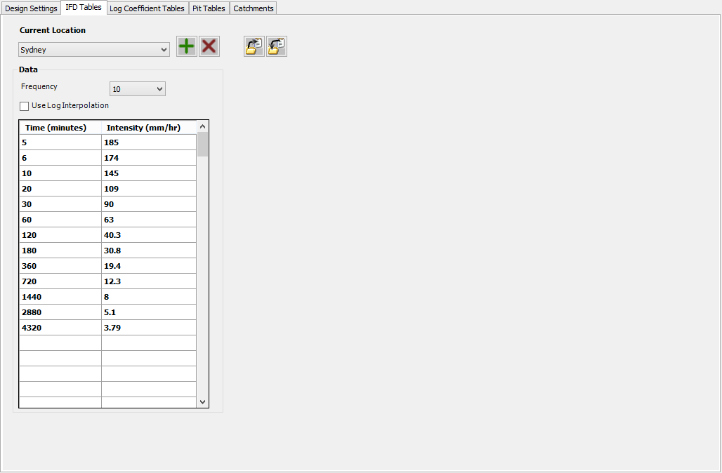
IFD Tables Tab
The Drainage - IFD Tables tab is used to define the Intensity Duration Frequency (IFD) tables for various locations. The a IFD location can be selected as the Design Storm for the drainage analysis in the Design Settings tab.
Note: To adjust the focus to show information about a different tab, just click on the tab of interest.
 |
|
| Current Location | Select the current IFD table to be viewed/edit. |
| New IFD Location |
Create a new IFD location. |
| Delete Current IFD Location |
Delete the current IFD location. The default IFD location can not be deleted. |
| Export Current IFD Location |
Export the current IFD location to file. See Importing & Exporting Tables below. |
| Import IFD Location |
Import a IFD location from file. See Importing & Exporting Tables below. |
| Data | Define the data for the current IFD location |
| Frequency | Select the desired frequency to be created/edited (0.25, 1, 2, 5, 20, 50 or 100). All frequencies do not have to be entered, however if a frequency is used in the Design Settings and no data is entered for it, then the software will report 0 for that frequency in any reports and long sections. Note: The 0.25 is intended to be used for the 'Low Flow' frequency. |
| Use Log Interpolation | Tick box to Enable or Disable the logarithmic interpolation of the IFD data. When this option is OFF, the software will use linear interpolation of the data. |
| Time (minutes) | Enter the time in minutes. |
| Intensity (mm/hr) | Enter the Intensity in millimetres per hour. |
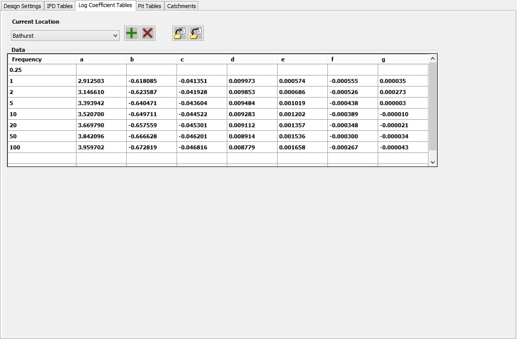
Log Coefficient Tables Tab
The Drainage - Log Coefficient Tables tab is used to define the Log Coefficient tables for various locations. The a Log Coefficient location can be selected as the Design Storm for the drainage analysis in the Design Settings tab.
Note: To adjust the focus to show information about a different tab, just click on the tab of interest.
 |
|
| Current Location | Select the current Log Coefficient table to be viewed/edit. |
| New Log Coefficient Location |
Create a new Log Coefficient location. |
| Delete Current Log Coefficient Location |
Delete the current Log Coefficient location. The default Log Coefficient location can not be deleted. |
| Export Current Log Coefficient Location |
Export the current Log Coefficient location to file. See Importing & Exporting Tables below. |
| Import Log Coefficient Location |
Import a Log Coefficient location from file. See Importing & Exporting Tables below. |
| Data | Define the data for the current Log Coefficient location |
| Frequency a b c d e f g | Enter the coefficients (a, b, c, d, e, f & g) for the various frequencies (0.25, 1, 2, 5, 20, 50 or 100). All coefficients for a specific frequency MUST be entered, however a specific frequency can be omitted. If data for a frequency does not exist and that frequency is used in the Design Settings, then the software will report 0 for that frequency in any reports and long sections. Note: The 0.25 is intended to be used for the 'Low Flow' frequency. |
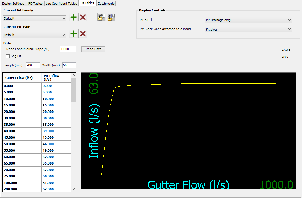
Pit Tables Tab
The Drainage - Pit Tables tab is used to define the pit family and types that can be used in the project for drainage pits.
In the software, individual pit are defined as a Pit Type and belong to a Pit Family.
When a pit of a defined drainage network is attached to a road the software will automatically change the pit type (excluding the null pit and all sag pits) to a pit within the same family with a Road Longitudinal Slope that best matches the longitudinal slope of the road the pit is attached to.
Note: To adjust the focus to show information about a different tab, just click on the tab of interest.
 |
|
| Current Pit Family | Select the current Pit Family to be viewed/edit. Note: Irrespective of the data entered, the Null pit family will use no pit data to represent a pipe to pipe connection. The Display Controls are still used. |
| New Pit Family |
Create a new Pit Family table. |
| Delete Current Pit Family |
Delete the current Pit Family table. Note: The 'Default' Pit Family table can not be deleted. |
| Export Current Pit Family |
Export the current Pit Family table to file. See Importing & Exporting Tables below. |
| Import Pit Family |
Import a Pit Family table from file. See Importing & Exporting Tables below. |
| Current Pit Type | Select the current Pit Type to be viewed/edit. Note: Irrespective of the data entered, the Null pit type will used no pit data to represent a pipe to pipe connection. The Display Controls are still used. |
| New Pit Type |
Create a new Pit Type. |
| Delete Current Pit Type |
Delete the current Pit Type. The default Pit Family location can not be deleted. |
| Display Controls | Define how the pit is displayed in the drawing. |
| Pit Block | Select the block used to represent the drainage pit in the drawing. The block is aligned to the downstream pipe when the drainage network is defined. The blocks are initially loaded from the CSD Common folder and then from the drawing. |
| Pit Block when Attached to a Road | Select the block used to represent the drainage pit in the drawing when it is attached to a road. The block is automatically aligned to the road centreline when the drainage network is defined. The blocks are initially loaded from the CSD Common folder and then from the drawing. |
| Data | Enter the performance data for the current pit. Pits are assumed to be On Grade pits unless the Sag Pit option is selected. |
| Road Longitudinal Slope (%) | Specify the road longitudinal slope as a percentage. This value is ignored when Sag Pit is selected. |
| Read Data | Users can read a Pit capture curve from a text table. When selected, Windows Explorer will open and allow the user to navigate to and select the appropriate file. The file should contain pairs of data separated by a comma on each line. The pairs of data should be either "Approach Flow, Pit Inflow" for On Grade Pits and "Gutter Depth, Pit Inflow" for Sag Pits. Note: The text file units are m³/s for flows and m for depths. |
| Sag Pit | When this option is checked, the pit is assumed to be a sag pit. This also controls the left hand side of the Input table below. |
| Length (mm) | Enter the length of the pit in millimetres. This value is can be used in the Long Section plots and Reports. |
| Width (mm) | Enter the width of the pit in millimetres. This value is can be used in the Long Section plots and Reports. |
| Gutter Flow (l/s) | For On Grade Pits only - Enter the gutter flow (arriving at the pit) in litres per second. |
| Gutter Depth (mm) | For Sag Pits only - Enter the gutter depth in millimetres (when Sag Pit is selected). |
| Pit Inflow (l/s) | Enter the pit inflow in litres per second. |
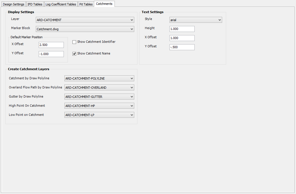
Catchments Tab
The Drainage - Catchments tab is used to configure how the drainage catchments are displayed and labelled.
Note: To adjust the focus to show information about a different tab, just click on the tab of interest.
 |
|
| Display Settings | Configure the display controls for drainage catchments. |
| Layer | Select the layer used to display drainage catchments (marker, label and connection line). Use the Edit Layer Settings command to edit the layers available. |
| Marker Block | Select the block used to represent the drainage catchment in the drawing. The blocks are initially loaded from the CSD common folder and then from the drawing. |
| Default Marker Position | Configure the default position of a catchment NOT associated with a polyline. |
| X Offset | Enter the X offset in drawing units from the pit. |
| Y Offset | Enter the Y offset in drawing units from the pit. |
| Show Catchment Identifier | Enable this option to show the catchment identifier in the drawing. |
| Show Catchment Name | Enable this option to show the catchment name in the drawing. |
| Text Settings | Configure the text settings used to show the catchment labels. |
| Style | Select the text style to be used. |
| Height | Enter the text height in drawing units. |
| X Offset | Enter the X offset in drawing units, from the catchment marker to place the label in the drawing. |
| Y Offset | Enter the Y offset in drawing units, from the catchment marker to place the label in the drawing. |
| Create Catchment Layers | Configure the layers applied for drawing the catchment area, flow line and gutter line. These controls are available when Creating/Editing Catchments. |
| Catchment by Draw Polyline | Select the layer used to display the catchment area. Use the Edit Layer Settings command to edit the layers available. |
| Overland Flow Path by Draw Polyline | Select the layer used to display the catchment flow line. Use the Edit Layer Settings command to edit the layers available. |
| Gutter by Draw Polyline | Select the layer used to display the gutter flow line. Use the Edit Layer Settings command to edit the layers available. |
| High Point on Catchment | Select the layer used to display the catchment high point text. Use the Edit Layer Settings command to edit the layers available. |
| Low Point on Catchment | Select the layer used to display the catchment low point text. Use theEdit Layer Settings command to edit the layers available. |
Sewer Tab
The Sewer tab is used to configure project settings specific to Sewer Networks. It is divided up into the following tabs (Click on a tab for more information about that tab):

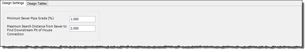
Design Settings Tab
The Sewer - Design Settings tab is used to configure the various design settings used for the creation of sewer networks.
Note: To adjust the focus to show information about a different tab, just click on the tab of interest.
 |
|
| Minimum Sewer Pipe Grade (%) | Enter the minimum grade for sewer networks. |
| Maximum Search Distance from Sewer to Find Downstream Pit of House Connection | Enter the distance in drawing units the software will search from a sewer network to find the downstream end of a house connection. |
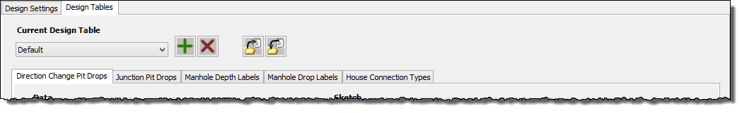
Design Tables Tab
The Sewer - Design Tables tab is used to configure the various design tables used when creating, plotting and reporting sewer networks.
Note: To adjust the focus to show information about a different tab, just click on the tab of interest.
 |
|
| Current Design Table | Select the current Design Table to be viewed/edit. |
| New Design Table |
Create a new Design Table . |
| Delete Current Design Table |
Delete the current Design Table . The default Design Table can not be deleted. |
| Export Current Design Table |
Export the current Design Table to file. See Importing & Exporting Tables below. |
| Import Design Table |
Import a Design Table from file. SeeImporting & Exporting Tables below. |
 |
There are several different sewer design tables as shown left. (Click on a tab in the image above for more information about that tab): |
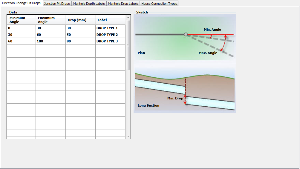
Direction Change Pit Drops Tab
The Sewer - Design Tables - Direction Change Pit Drops tab is used to define the Direction Change design tables. This table is used when creating or updating a sewer networks to control the drop through a direction change pit (1 incoming pipe only).
Note: To adjust the focus to show information about a different tab, just click on the tab of interest.
 |
|
| Data | Define the data for the Direction Change table. |
| Minimum Angle | Specify the minimum angle in degrees. |
| Maximum Angle | Specify the maximum angle in degrees. |
| Drop (mm) | Specify the pit drop to apply in millimetres. |
| Label | Enter the label required to identify the drop applied. |
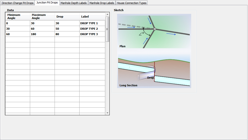
Junction Pit Drops Tab
The Sewer - Design Tables - Junction Pit Drops tab is used to define the Junction Drop design tables. This table is used when creating or updating a sewer networks to control the drop through a junction pit (2 or more incoming pipes).
Note: To adjust the focus to show information about a different tab, just click on the tab of interest.
 |
|
| Data | Define the data for the Junction Drop table. |
| Minimum Angle | Specify the minimum angle in degrees. |
| Maximum Angle | Specify the maximum angle in degrees. |
| Drop | Specify the pit drop to apply in millimetres. |
| Label | Enter the label required to identify the drop applied. |
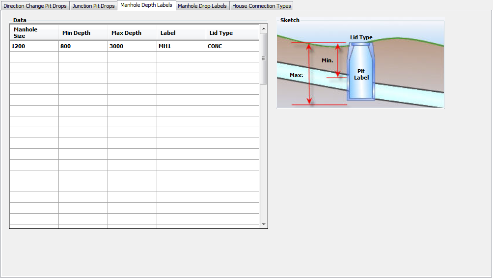
Manhole Table Depth Labels Tab
The Sewer - Design Tables - Manhole Depth Labels tab is used to define the Manhole depth design tables. This table defines the lid type and manhole to use based on the pit depth.
Note: To adjust the focus to show information about a different tab, just click on the tab of interest.
 |
|
| Data | Define the data for the Manhole table. |
| Manhole Size | Specify the manhole size in millimetres. |
| Min Depth | Specify the minimum manhole depth from top of pit to sump in millimetres. |
| Max Depth | Specify the maximum manhole depth from top of pit to sump drop in millimetres. |
| Label | Specify the label. |
| Lid Type | Specify the manhole lid type. |
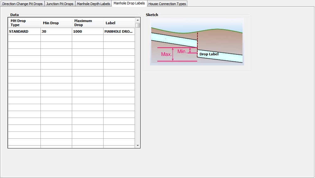
Manhole Drop Labels Tab
The Sewer - Design Tables - House Connection Types tab is used to label the house connections based on the depth from the house connection invert at the sewer down to the final connection at the sewer pipe. This information can be included in long section plot outputs.
Note: To adjust the focus to show information about a different tab, just click on the tab of interest.
 |
|
| Data | Define the data for the Manhole Drop table. |
| MH Drop Type | Specify the manhole drop type. |
| Min Drop | Specify the minimum drop in millimetres. |
| Maximum Drop | Specify the maximum drop in millimetres. |
| Label | Specify the label. |
House Connection Types Tab
The Sewer - Design Tables - Manhole Drop Labels tab is used to define the Manhole depth design tables. This table is to identify different drop structures required based on the depth of drop through the pit.
Note: To adjust the focus to show information about a different tab, just click on the tab of interest.
 |
|
| Data | Define the data for the House Connection Types table. |
| House Connection Type | Specify the house connection type for the specified drop range (ranging From Drop To Drop). |
| From Drop (mm) | Specify the minimum drop in millimetres. |
| To Drop (mm) | Specify the maximum drop in millimetres. |
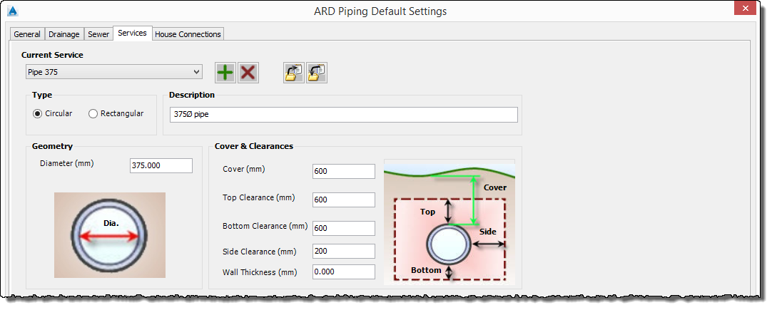
Services Tab
The Services tab is used to configure the settings for service obstructions.
Note: To adjust the focus to show information about a different tab, just click on the tab of interest.
 |
|
| Current Service | Select the current Service Obstruction to be viewed/edit. |
| New Service |
Create a new Service Obstruction. |
| Delete Current Service |
Delete the current Service Obstruction. The default Service Obstruction can not be deleted. |
| Export Current Service |
Export the current Service Obstruction to file. See Importing & Exporting Tables below. |
| Import Service |
Import a Service Obstruction from file. See Importing & Exporting Tables below. |
| Type | Select the service obstruction type, either Circular or Rectangular. The image of the section will change pending the selection. |
| Description | Enter a description for the service obstruction type. This is reportable on the long section plotting and reporting. |
| Geometry | Define the geometric properties. |
| Diameter (mm) | Specify the diameter of the circular service obstruction in millimetres. Only visible when Circular type is selected. |
| Height (mm) | Specify the height of the rectangular service obstruction in millimetres. Only visible when Rectangular type is selected. |
| Width (mm) | Specify the width of the rectangular service obstruction in millimetres. Only visible when Rectangular type is selected. |
| Cover & Clearances | Set the cover and clearances. |
| Cover (mm) | Set the minimum cover in millimetres. |
| Top Clearance (mm) | Set the top clearance from the outside of the service obstruction in millimetres. |
| Bottom Clearance (mm) | Set the bottom clearance from the outside of the service obstruction in millimetres. |
| Side Clearance (mm) | Set the side clearance from the outside of the service obstruction in millimetres. |
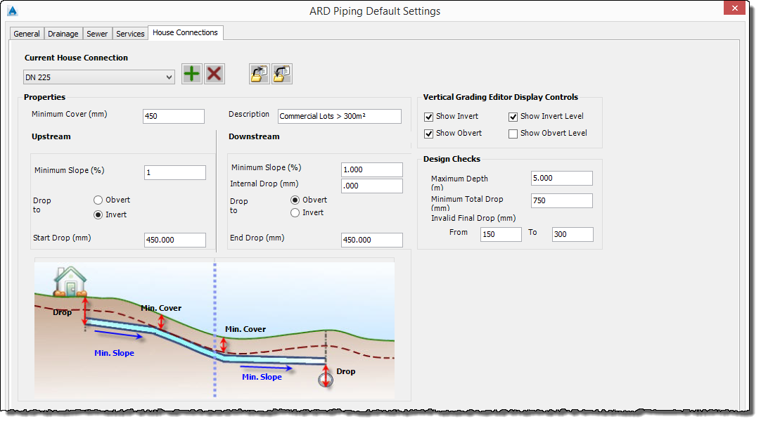
House Connections Tab
The House Connections tab is used to configure the design settings for the creation of house connections.
House connections are used as a constraint to assist in designing the drainage and sewer networks. The user should adopt a naming convention to distinguish between the two (2) different house connections that can be used.
Note: To adjust the focus to show information about a different tab, just click on the tab of interest.
 |
|
| Current House Connection | Select the current House Connection to be viewed/edit. |
| New House Connection |
Create a new House Connection. |
| Delete Current House Connection |
Delete the current House Connection. The default House Connection can not be deleted. |
| Export Current House Connection |
Export the current House Connection to file. See Importing & Exporting Tables below. |
| Import House Connection |
Import a House Connection from file. See Importing & Exporting Tables below. |
| Properties | Define the design properties for the current house connection. |
| Minimum Cover (mm) | Specify the minimum cover in millimetres. |
| Description | Type in a description for the House Connection Type. This can be reported at the time of plotting House Connections during Long Section Plotting. |
| Upstream | Define the house connection upstream design controls. |
| Minimum Slope (%) | Specify the minimum slope in percentage. |
| Drop to | Define how the initial drop is defined. Select either Invert or Obvert. |
| Start Drop (mm) | Specify the initial drop in millimetres. |
| Downstream | Define the house connection downstream design controls. |
| Minimum Slope (%) | Specify the minimum slope in percentage. |
| Internal Drop (mm) | Specify the internal drop in millimetres. This is the drop applied when the house connection is create with an Internal Drop/Frontage Line control, at the Frontage Line. |
| Drop to | Define how the final drop is defined. Select either Invert or Obvert. |
| End Drop (mm) | Specify the end drop in millimetres. This represents the nominal drop required to enter the sewer pipe and acts a constraint level for the sewer design. The Final drop is subject to the sewer levels adopted. |
| Vertical Grading Editor Display Controls | Define how the house connection is displayed in the Vertical Grading Editor (VGE). At least one of the options should be enabled to show the house connection in the VGE |
| Show Invert | Enable or disable the display of the house connection invert on the VGE. |
| Show Invert Level | Enable or disable the display of the house connection invert level text on the VGE |
| Show Obvert | Enable or disable the display of the house connection obvert on the VGE. |
| Show Obvert Level | Enable or disable the display of the house connection obvert level text on the VGE |
| Design Checks | Indicates to the user if the house connection depths or drops are outside of a user defined range |
| Maximum Depth (m) | Specify a maximum depth value for the house connection in metres. This value represents the depth of the house connection outlet at the connection with sewer pipe. The user will be alerted if the maximum depth is violated, both at the time of creation and in a Sewer House Connections Report. |
| Minimum Total Drop (mm) | Specify a minimum total drop value for the house connection in millimetres. This value represents the level difference from the finished surface level (FSL) at the start of the house connection and the invert of the sewer at the house connection outlet. The user will be alerted if the minimum total drop is not achieved in a Sewer House Connections Report. |
| Invalid Final Drop (mm) | Specify a range defining invalid drop values from the house connection to the sewer pipe. The range of invalid drops is specified by setting the range of drop values in the From and To fields. The user will be alerted if the drop values fall within this range in a Sewer House Connections Report. |
| From | Specify a value representing a minimum invalid drop in millimetres. |
| To | Specify a value representing a maximum invalid drop in millimetres. |
Importing & Export Tables
Any of the design tables used in the Active Network Settings form can be exported to and imported from file. This is the best way to transfer a table to another project or to the Global Network Settings.
The design tables that can be exported and imported are:
- Pipe Tables (.ardPipes)
- Box Sections Tables (.ardBoxSections)
- Drainage IFD Tables (.IFDCoeffs)
- Drainage Log Coefficient Tables (.logCoeffs)
- Drainage Pit Tables (.ardPits)
- Sewer House Connections (.houseCon)
- Sewer Design Tables (.sewDesign)
- Service Obstructions (.services)
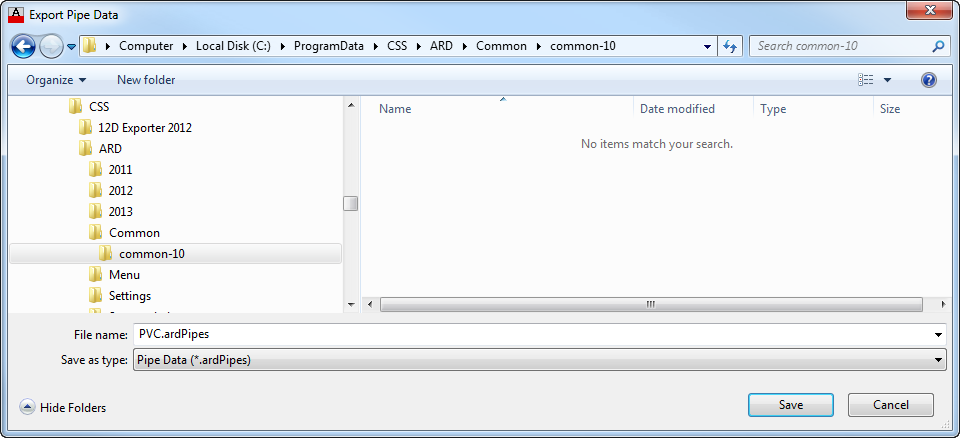
Exporting
When you choose to export any design table to a file a form, similar to the one below, is displayed. The Window header and Save as File Type will change to identify what type of Design Table is being exported.
|
|
|
| Save in | Specify the folder the file will be save to. |
|
File name |
Specify the filename. By default the name will be the same as the table being exported. Specifying different name will also set the name of the exported table as well as the file name. |
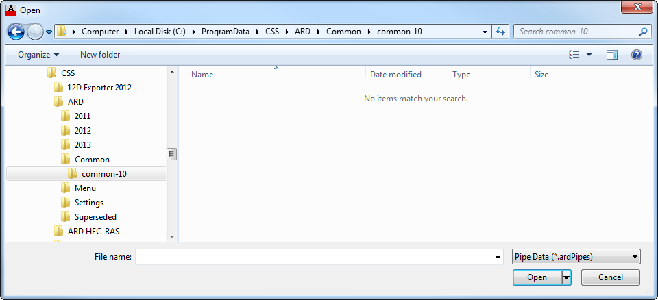
Importing
When you choose to import any design table from a file a form, similar to the one below, is displayed. The Window header and File Type will change to identify what type of Design Table is being imported.
 |
|
| Look in | Specify the folder the file can be found in. |
| File name | Specify the file (design table) to import. |