Pipe Design Bypass Method
| Icon: | |
| Menu: | CSD Pipes > Settings > Bypass Method |
| Ribbon: | Pipes Tab > Settings Panel Slideout > Bypass Method |
Introduction
This command is used to set the way Bypass is treated with respect to Pipe flow. There are three (3) methods, along with the ability to change the method on existing networks.
Bypass flows are calculated for pits and are stored separately to those for pipe flows.
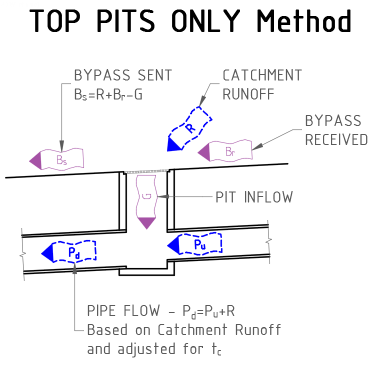
The Top Pits Only method, forces all catchment runoff into the downstream pipe, with the exception for Top Pit, where the pipe flow is based on the Pit Inflow. In others words bypass flows are ignored when designing pipes.
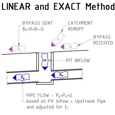
The two (2) other methods are provided to better treat these bypass flows - Linear and Exact. These methods are the same, expect for time calculations. For larger networks, Linear should produce faster results as the User can enter the time interval.
Details
Upon selecting this command, the designer must select a network. This can be achieved by either selecting the network in the drawing or from a list. Click here for more details on selecting a network.
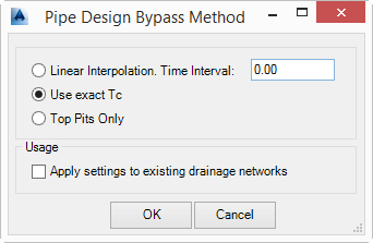
After a network has been selected the Pipe Design Bypass Method window will appear, the User then must select one (1) of the three (3) methods and choose whether to apply it to an existing network(s). The method selected then becomes the method applied to any new drainage network.
 |
|
| METHOD | Users must select from one (1) of the three (3) methods. |
| Linear Interpolation. Time Interval: | Selecting this method, the user is required to enter a Time Interval in minutes. The software will pre-calculate the bypass flows between the minimum and maximum times of concentration set, with the interval specified. As the bypass flows are pre-calculated, this method should produce faster results on larger stormwater networks. |
| Use Exact Tc | When this method is used, the exact time of concentration is calculated each and every time it is needed. With complex bypass and pipe configurations, this could result in some performance issues. Should this ‘lag’ be considered excessive to the User, perhaps the Linear method should be used. |
| Top Pits Only | For the first (top) pipe of any branch that has surface flow only, without receiving any bypass flows, the pipe flow will match the pit inflow. On any other pit, all of the surface flow (catchment runoff) excluding any bypass flow received, becomes the adopted pipe inflow. Should the pit generate a bypass flow, this bypass flow is passed onto the nominated pit, however this bypass flow is ignored and forced into the pipe. That is bypass flows are ignored from the pipe’s point of view, but not from the pit calculations. |
| Usage | This allows the method to be altered on an existing network. |
| Apply settings to existing drainage networks | This option allows the User to change the bypass method for existing network(s). The method selected above will be applied to those networks selected when the command was started. |
| OK | Apply and exit - the method set will then be applied to any new drainage network. |
| Cancel | Exit the form. |
Diagrams
The following diagrams present graphically and with equations what happens with the typical flows at every pit. The top pit of any branch is similar, except that there is no upstream pipe and potentially no bypass recieved.
 |
 |
Note - Interaction with Specified Inflows
Specified Inflows are also affected by the Bypass Method selected. Specified inflows can be directed to Pipe Only, Pit and Pipe or Pit Only (No pipe flow). A simplex matrix of the interaction between them is shown in the table below.
| Top Pits Only | Linear or Exact | |
| Pipe Only | Adds to Outlet Pipe Only | Adds to Outlet Pipe Only |
| Pit and Pipe | Adds to Pit and Outlet Pipe | Do Not Use |
| Pit Only (No Pipe) | Adds to Pit, but NOT Outlet Pipe flow | Adds to Pit, then Outlet Pipe based on Pit Capacity |