Vertical Grading Editor
| Icon: | |
| Menu: | CSD Pipes > Vertical Grading Editor |
| Ribbon: | Pipes Tab > Edit Panel > VGE |
Introduction
The Pipes Vertical Grading Editor is one of the central design features of the software and facilitates the vertical grading of your pipe and pit networks.
To edit the vertical grading of pipes and pits, users start the command and select an upstream pit - the software traces the branch from the upstream pit to the downstream outlet and presents this in the Vertical Grading Editor window.
Multiple pipe/pit branches can be designed simultaneously for any pipe/pit network and interact dynamically with all other pipe/pit networks, including underground service obstructions - this enables the designer to see 'real time' the effect of changing the vertical grading of a pipe/pit on all related pipes and pits across multiple networks.
Pre-Requisites
In order to edit pipes and pits the designer must first have created a Network of the pipe and pit collection.
This command is normally preceded by the Create/Edit Network command. In the case of House Connections and Service Obstructions, a network is created immediately upon creation of these pipe types.
It is recommended also that the Branch Sequence command and Network Labelling Settings commands are executed after creating the network - this allows for branching of the network to be determined as well as the pits and/or pipes to be labelled based on the branch and pit sequencing.
Pipes Vertical Grading Editor - Display
A view of the Vertical Grading Editor is shown, below. Borders and text have been added to highlight the main functional components of the form. Click on a command button or view window from the image for more information:

The main components of the Vertical Grading Editor is as follows (click on the image shown to focus on the details of these tools):
| Vertical Grading Design Window | This is the main window displaying the long section of the selected pipe branch: 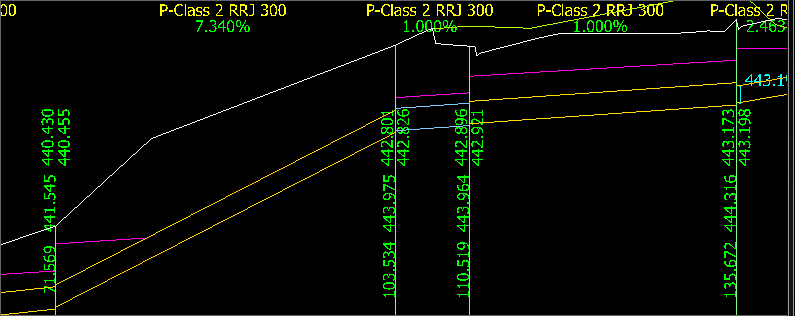 |
| Pipe/Pit Editing Tools | This collection of tools facilitates editing of the highlighted pipe and the downstream and upstream pit: 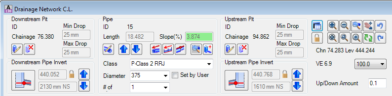 |
| Reporting Panel | This part of the Pipes Vertical Grading Editor enable save and exit of the editor as well as notifying users of any active commands: 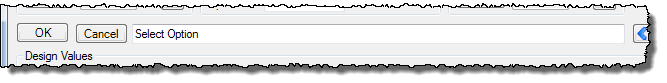 |
| Navigation Tools | This collection of tools facilitate zooming/panning in the drawing, navigation to the next upstream/downstream pipe and sets the increment to raise pipes and pits by (action via the Pipe/Pit Editing Tools) 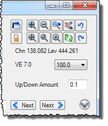 |
| Pipe Data Panel | This is a collapsible/expandable panel displaying selected geometric, hydraulic and hydrology values for a selected pipe. The data displayed will be subject to the type of Pipe Network created 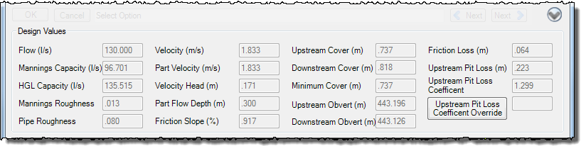 |
Starting the Vertical Grading Editor
Upon selecting this command, at the Command prompt the user will be asked to "Select Pit on a Network or Press <Enter> to Select from a Network and then a Pit Number".
There are two methods for selecting a part of the network to edit in the Vertical Grading Editor.
Users can either:
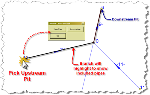
| Graphically Select a Pit on the Network | Graphically select the upstream pit that represents the branch required to be edited using the left mouse button. Upon selecting an upstream pit the software will highlight the pipes to the downstream pit and the following form is displayed:
If an error is made selecting a pit, users can close the form by clicking on the x at the top right of the form and selecting a different pit at the command prompt. At the prompt to select a pit in the drawing, press Esc or Enter to stop the command and not open a Pipes Vertical Grading Editor window to edit pipes/pits. |
||||||||
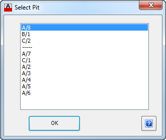
| Select a Pit from a List | Press <Enter> at the command prompt to select a network At the command prompt "Locate Network Required" the user must graphically select a pipe or pit on the required network.
Upon selecting a pipe or pit the following form is displayed:
|
||||||||
Common Issues When Selecting a Pit
The following issues and prompts can result when selecting a pit for presentation of a pipe branch in the editor:
Error Message |
Cause |
||||
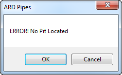 |
The mouse selection point is too far from the location of a pit in the drawing - the software has not detected any pit within the required distance from the selected point. Form details are as follows:
|
||||
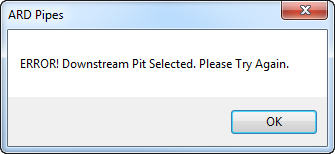 |
The designer has selected the most downstream pit in a network. As the software is tracing pits working from the upstream pit to the downstream pit, it is unable to located pipes/pits to present in the Pipes Vertical Grading Editor window. Form details are as follows:
|
Initial Display Controls and General Features
When the Pipes Vertical Grading Editor is first opened it displays as follows:
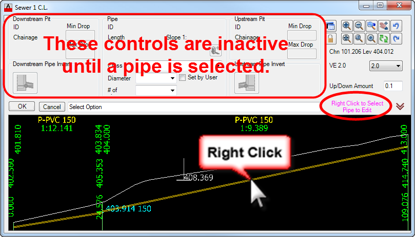
Users are expected to select a pipe in the lower display window to start the editing and design review process. Hover over a pipe in the lower display window and click the right mouse button to select the pipe for editing.
The Design Values frame contains a collection of geometric, hydraulic and hydrology data important to pipe designers, especially in the design of stormwater/drainage gravity systems. To suppress the display of the Design Values frame, designers can click on the ![]() Hide Data icon. The icon will change display and designers can click on the
Hide Data icon. The icon will change display and designers can click on the ![]() Expand Data icon to re-display the Design Values frame.
Expand Data icon to re-display the Design Values frame.
There are a number of benefits to using the Pipes Vertical Grading Editor. They include:
- Re-scalable Form - change the vertical exaggeration and width of the form simply by dragging at the corner of the window
- Always on Top - the form is always on top, except when an CSD, AutoCAD or Civil 3D command is detected, when it will momentarily minimise
- Dynamic Updating - multiple pipe network branches can be viewed in separate Pipes Vertical Grading Editor windows and crossing pipes are dynamically represented on each VGE window.
- Pipe Grading Tracker - the software includes a 'tracker' in the model space to display the current location when hovering inside a Pipes Vertical Grading Editor window
| The green 'tracker' symbol traces along the pipe to show the designer the current location in the model whilst vertically grading the pipe network branch. |
Command Controls
Below are all the command and display controls of the Pipes Vertical Grading Editor.
The Pipes Vertical Grading Window |
|

The portion of the Vertical Grading Editor form provides a vertical representation of the pipe and pit branch selected. It is used to select the pipe to edit, as well as setting the location for inserting new pits and co-ordinating the plan marker.
Display Controls
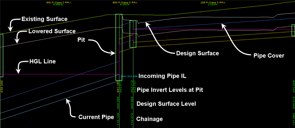
Pipes are displayed graphically and pits are identified with a vertical line. The Pipes Vertical Grading Window displays the following information:
| Text | Colour(s) |
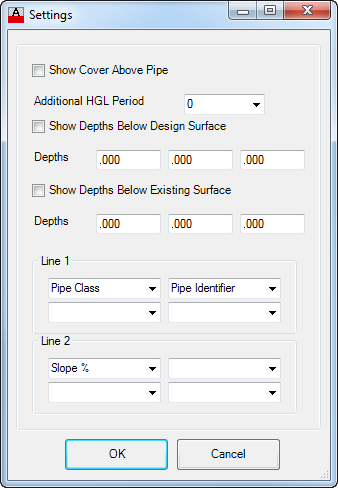
| Pipe grades, pipe slope, number of pipes, pipe class and/or pipe identifier (displayed at the top of the window). Note: The information displayed is configurable from the Display Settings form. | Yellow, Green, Green |
| Chainage, top of pit level and pipe invert (displayed at the pits on a 90° angle) | Green |
| Surface Display | |
| Existing Surface | Green |
| Design Surface | White |
| Surface at Depth (from Existing surface or Design Surface) | Varies |
| Branch Pipe and Pit Display | |
| Pit centreline vertical line | Green |
| Pipes (invert and obvert) and pits of the selected branch | Yellow, Light Yellow |
| Pipe clearance (cover) line (display control on/off) | Yellow |
| The current pipe highlighted for editing is highlighted | Light Blue |
| Crossing Pipes and Service Obstructions | |
| Incoming and outgoing pipes to a pit are denoted with a ] symbol and text describing the invert level of the pipe and the pipe diameter, separated by a space. | Cyan |
| Crossing Pipes (including clearances) that do not cross the design pipe | Dark Blue |
| Service Obstructions (including clearances) that do not cross the design pipe | Pink |
| Crossing pipes and Service Obstructions that interfere (are inside the clearance) with the design pipe | Red |
| For Drainage Networks | |
| Hydraulic Grade Line (HGL) displayed for the design storm (minor storm, by default) | Magenta |
| Hydraulic Grade Line (HGL) displayed for a user selected storm | Pink |
| Pit Surcharge - a number will be displayed above a pit. This value represents the lowest ARI resulting in pit surcharge at that pit location. Only the most upstream surcharging pit will be displayed | Red |
| For Sewer Networks | |
| House/Property Connections and text | Grey |
Edit Controls
Click on the right mouse button when hovered over a pipe to select it for editing. Alternately use the ![]() Show Previous or
Show Previous or ![]() Show Next icons to highlight the preceding/next pipe for editing.
Show Next icons to highlight the preceding/next pipe for editing.
The window is also used to:
- graphically select the position to insert a new pipe/pit after the
 button is selected.
 - graphically select the upstream or downstream end of a pipe to adjust it to match the obvert of the next upstream/downstream pipe at the nearest pit after the
 button is selected.
Pipe and Pit Editing Tools |
|
For any selected pipe, the Pipe and Pit Editing Tools allow the user to:
- Edit the upstream and/or downstream pipe elevations
- Edit the pipe grade and pipe type
- Edit the upstream and/or downstream pits joining the pipe
- Insert in-line pits in the network where required
Note: The 'downstream' and 'upstream' pits are more accurately described as the ''pit at start of pipe" and "pit at end of pipe" - users are able to edit the pipe elevations for the pipe fall to change flow direction to be away from the appointed 'downstream pit'.
For a selected pipe, there are three components that can be edited:
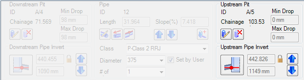
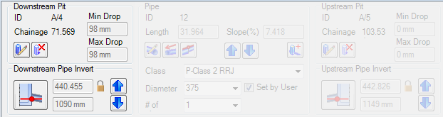
Downstream Pit |
Displays details regarding the downstream pit as well as providing tools to edit or delete the pit |
||||||||||||||||||||||||
ID |
This displays the pit identifier. |
||||||||||||||||||||||||
| Chainage | This displays the chainage of the pit, measured from the downstream outlet pit. | ||||||||||||||||||||||||
| Min Drop | This displays the minimum drop (mm) of all pipes connected to this pit. | ||||||||||||||||||||||||
Max Drop |
This displays the maximum drop (mm) of all pipes connected to this pit. |
||||||||||||||||||||||||
| |
Click to edit the pit properties including pit top level, pit bottom level and pipe level constraints.
|
||||||||||||||||||||||||
| |
Click on this icon to delete the downstream pit of the highlighted pipe. A confirmation message will display - click OK to confirm deletion of the pit. Note: users will not be permitted to delete a pit at a junction, the downstream pit or pit immediately preceding the downstream pit. Error messages will display for these occurrences and the pit will not be deleted. Click OK to exit the forms. | ||||||||||||||||||||||||
| Downstream Pipe Invert | Edit the pipe elevation at the downstream pit | ||||||||||||||||||||||||
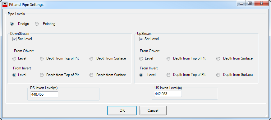
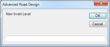
| |
Clicking on this icon enables manual setting of the pipe invert:
|
||||||||||||||||||||||||
| Pipe Invert Level | This greyed out field describes the current invert of the pipe, measured at the pit centreline | ||||||||||||||||||||||||
| Depth to Invert | This greyed out field describes the depth to invert for the pipe, taken as the distance from the pipe invert to the nominated Design surface and measured at the pit centreline. | ||||||||||||||||||||||||
 Lock Icon (Level Set by User) Lock Icon (Level Set by User) |
Indicates that the user has manually set the elevation of the downstream pipe at the pit. This icon will only display if the user has manually set the elevation of the downstream pipe. Note: Users can revert to the default design settings for the pipe elevation from the Edit Pipe Properties or Set/Clear Lock Status on Pipes commands. | ||||||||||||||||||||||||
| |
Move the pipe up by the Up/Down Increment (m) value. Note: if the pipe level has been set as a depth to the top of pit or a depth to surface the user will be prompted to override this control. | ||||||||||||||||||||||||
| |
Move the pipe down by the Up/Down Increment (m) value. Note: if the pipe level has been set as a depth to the top of pit or a depth to surface the user will be prompted to override this control. | ||||||||||||||||||||||||
Up/Down Increment (m)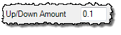 |
The amount that the pipe end will raise/lower upon selection of the |
||||||||||||||||||||||||
 |
|||||||||||||||||||||||||
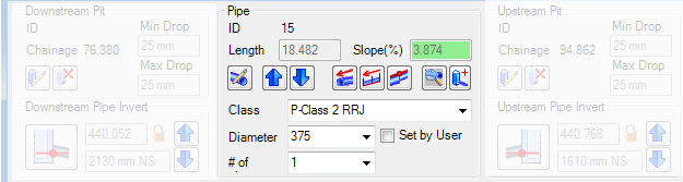
| Pipe | Edit the pipe elevations, the pipe size and type and the pipe grade. Insert new pits in the pipe. | ||||||||||||||||||||||||
| ID | This displays the pipe number assigned by the software. | ||||||||||||||||||||||||
| Length | This displays the pipe length and is a non-editable field. | ||||||||||||||||||||||||
| Slope (%) or Slope 1: | This displays the pipe grade (%) or pipe slope (1:) and is a non-editable field. Note: The method of slope input is controlled via the Active Network Settings form. Users can select the slope input method pending the network type. | ||||||||||||||||||||||||
| |
 Excepting extra controls in the Edit Pipe Properties command to edit the Pipe Class, Pipe Item and Number of Pipes, this form matches the functionality as described in the Edit Pipe Properties command. Click on the image or click here to view the details of this command. |
||||||||||||||||||||||||
| |
Move the entire pipe up by the Up/Down Increment (m) value. Note: if the pipe level at either end has been set as a depth to the top of pit or a depth to surface the user will be prompted to override this control |
||||||||||||||||||||||||
| |
Move the entire pipe down by the Up/Down Increment (m) value. . Note: if the pipe level at either end has been set as a depth to the top of pit or a depth to surface the user will be prompted to override this control |
||||||||||||||||||||||||
| Up/Down Increment (m) |
The amount that the pipe will raise/lower upon selection of the |
||||||||||||||||||||||||
| |
Click on this icon to open the following form:
|
||||||||||||||||||||||||
|
|
Click on this icon to open the following form:
|
||||||||||||||||||||||||
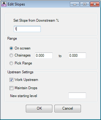
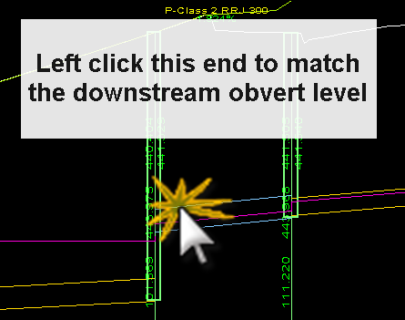
Click on this icon to edit the upstream or downstream end of a pipe to match the obvert level of the next upstream or downstream pipe at the pit. This command works on any pipe displayed in the Vertical Grading Editor window, except for the upstream end of the most upstream pipe or the downstream end of the most downstream pipe shown in the Vertical Grading Editor. Upon selecting this command prompt in the Vertical Grading Editor Reporting Panel will prompt 'Select Level to Change (just Downstream or just Upstream of Pit)'. Use the mouse to graphically and click the left mouse button to select one end of a pipe that is located close to a pit to change and set the obvert level of that end of the pipe. The obvert level will be adjusted to match the obvert level of the next downstream (if the downstream end of the pipe was selected) or upstream (if the upstream end of the pipe was selected) pipe located at the pit. An example of the command is shown, below:
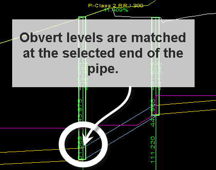
Upon completion of the command the end of the pipe will have it's obvert level set to match. This will set the pipe level for the end of the pipe that is selected. Note: If the next upstream or downstream pipe does not have its level at the pit set then the upstream or downstream pipe may be further adjusted after the obverts are matched to maintain either the cover, pit drop, minimum grade, capacity or velocity controls. If the next upstream or downstream pipe is adjusting so the obverts do not match you will need to set the levels of this end of the pipe. |
|||||||||||||||||||||||||
| |
Click on this icon to insert a new pit in line with the currently highlighted pipe. Upon selecting this icon the command prompt in the Vertical Grading Editor Reporting Panel will prompt 'Select Pit Insert Position'. Use the mouse to graphically position a location for the pit and click the left mouse button to make the selection. Note: Selecting a location in the Vertical Grading Editor window that is not within the chainage range of the currently highlighted pipe will result in an error message being displayed and the pit will not be inserted. Click OK to exit the message and restart the command. Upon selecting a valid location for the pit the following form will display.
Review the assigned pit family and pit type applied. The assigned Pit Family and Pit Type is controlled from the Active Network Settings. |
||||||||||||||||||||||||
| Class | This displays the Pipe Class. Use the pick list to select the required Pipe Class. | ||||||||||||||||||||||||
| Diameter | This displays the Pipe Identifier. Use the pick list to select the required Pipe Identifier. | ||||||||||||||||||||||||
| # of Pipes | This displays the number of parallel pipes being applied. This cell cannot be edited in the Vertical Grading Editor. To increase the number of parallel pipes being applied, exit the Vertical Grading Editor and start the Edit Pipe Properties command. | ||||||||||||||||||||||||
| Set by User | This is a toggle button. It is automatically ticked on if the user selects a particular Pipe Class and/or Pipe Diameter and/or sets the number of pipes. To restore the system to automatically assign the appropriate pipe size, untick the Set box. |
||||||||||||||||||||||||
 |
|||||||||||||||||||||||||
Upstream Pit |
Edit the pipe elevations at the upstream pit, move the upstream pipe up/down by increments, edit the pit properties or delete the pit |
||||||||||||||||||||||||
| ID | This displays the pit number/name | ||||||||||||||||||||||||
| Chainage | This displays the chainage of the pit, measured from the downstream outlet pit | ||||||||||||||||||||||||
| |
Click to edit the pit properties including pit top level, pit bottom level and pipe level constraints 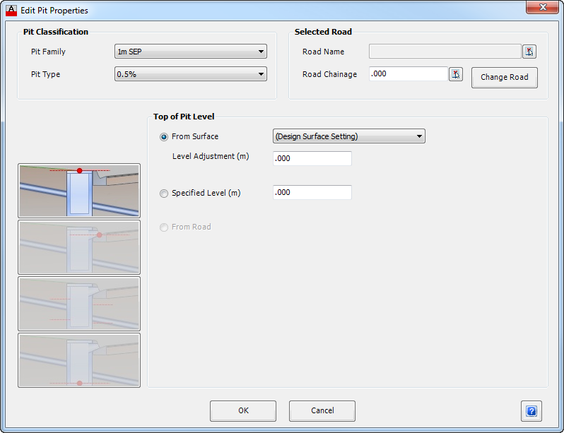 The functionality in this form matches the functionality as described in the Edit Pit Properties command EXCEPT that the pit plan location control is disabled. Click on the image or click here to view the details of this command. |
||||||||||||||||||||||||
| |
Click on this icon to delete the upstream pit of the highlighted pipe. A confirmation message will display - click OK to confirm deletion of the pit. Note: users will not be permitted to delete a pit at a junction, the downstream pit or pit immediately preceding the downstream pit. Error messages will display for these occurrences and the pit will not be deleted. Click OK to exit the forms. | ||||||||||||||||||||||||
| Upstream Pipe Invert | Edit the pipe elevation at the upstream pit | ||||||||||||||||||||||||
| |
Clicking on this icon enables manual setting of the pipe invert:
|
||||||||||||||||||||||||
| Pipe Invert Level | The greyed out number describes the current invert of the pipe, measured at the pit centreline. | ||||||||||||||||||||||||
| Depth to Invert | This greyed out field describes the depth to invert for the pipe, taken as the distance from the pipe invert to the nominated Design surface and measured at the pit centreline. | ||||||||||||||||||||||||
| Lock Icon (Level Set by User) |
Indicates that the user has manually set the elevation of the upstream pipe at the pit. This icon will only display if the user has manually set the elevation of the upstream pipe. Note: users can revert to the default design settings for the pipe elevation from the Edit Pipe Properties or Set/Clear Lock Status on Pipes commands. | ||||||||||||||||||||||||
| |
Move the pipe up by the Up/Down Increment (m) value. Note: if the pipe level has been set as a depth to the top of pit or a depth to surface the user will be prompted to override this control | ||||||||||||||||||||||||
| |
Move the pipe down by the Up/Down Increment (m) value. Note: if the pipe level has been set as a depth to the top of pit or a depth to surface the user will be prompted to override this control | ||||||||||||||||||||||||
| Up/Down Increment (m) |
The amount that the pipe start will raise/lower upon selection of the |
||||||||||||||||||||||||
 or
or 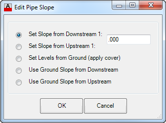
Reporting Panel |
|
|
|
| Command Line | The prompt in the command line change as commands are selected. This field alerts the user when an input is required from the user. |
| OK | Apply all changes in the Pipes Vertical Grading Editor and exit. |
| Cancel | Exit the form without applying changes made in the Pipes Vertical Grading Editor window. |
Navigation Tools |
|
The Navigations Tools primarily facilitate control of what is displayed in the Pipes Vertical Grading Window. The navigation tools and command details are as follows:
|
|||||||||||||||||||||||||||||
The following form is displayed and inputs are as follows:
|
|||||||||||||||||||||||||||||
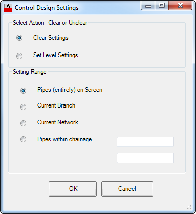
 Set/Clear Lock Status on Pipes Set/Clear Lock Status on Pipes |
The software will automatically assign pipe elevations based on geometric and hydraulic (for drainage networks) or house/property connection (for sewer network) controls. Users often want to manually set the pipe elevations.
This form enables quick removal or application of user override control of the pipe elevations and diameters. The following form is displayed and inputs are as follows:
|
||||||||||||||||||||||||||||
| Zoom in by 25% | |||||||||||||||||||||||||||||
| Zoom out by 25% | |||||||||||||||||||||||||||||
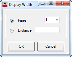
| This zoom enables the user to zoom to a selected number of pipes to be displayed in the Vertical Grading window. The following form is displayed and inputs are as follows:
Use the toggle options to select whether to zoom to a number of pipes or a set distance
|
|||||||||||||||||||||||||||||
| Select this to pan in the drawing. Click two locations to complete the pan action. Note: If no command is active, the middle mouse button works as a pan | |||||||||||||||||||||||||||||
| Zoom to the full extents of the pipes selected for the Vertical Grading Window | |||||||||||||||||||||||||||||
| Click twice to select the corners of the window to zoom to. | |||||||||||||||||||||||||||||
| Repositions the centre of the window display to the selected location. | |||||||||||||||||||||||||||||
| Refreshes the display of all pipes and pits in the window. | |||||||||||||||||||||||||||||
| Undo previous actions taken in the current session of the Pipes Vertical Grading Editor. | |||||||||||||||||||||||||||||
| Redo previous actions undone using the Undo command, above | |||||||||||||||||||||||||||||
| Chainage and Level | This is descriptive information of the current mouse location within the Vertical Grading window. Chainage is as measured from the downstream pit (outlet) Chn describes the chainage. Lev describes the level. | ||||||||||||||||||||||||||||
| Vertical Exaggeration | The current vertical exaggeration is noted by VE and followed by a number - this represents the current exaggeration applied. Use the pick list to select a preferred vertical exaggeration. | ||||||||||||||||||||||||||||
| Up/Down Increment (m) |
This is the amount that pipes are raised/lowered when the raise/lower (by increment) commands are applied in the pipe/pit editing tools. | ||||||||||||||||||||||||||||
| Click to highlight the next upstream pipe for editing | |||||||||||||||||||||||||||||
| Click to highlight the next downstream pipe for editing | |||||||||||||||||||||||||||||
Pipe Design Panel |
|
The Pipe Design Tools provide important reporting information regarding the pipe geometry as well as the pipe hydraulics. The data displayed in this expandable form will be subject to the type of Network being created - only the Drainage network includes data reporting on the pipe hydraulics.
|
|||||||||||
| If the Design Values are not displayed, click on this icon to expand the form to display the Design Values. | |||||||||||
 Hide Data Hide Data |
When the Design Values are displayed, click on this button to hide them | ||||||||||
| Design Values | Excepting the pit loss coefficient override, this is a collection of non-editable reporting fields describing the pipe attributes. | ||||||||||
| Flow (l/s) | Drainage Networks - Calculated flow from the hydrology | ||||||||||
| Mannings Capacity (l/s) | Drainage Networks - Pipe Flow capacity calculated using the Manning's formula for calculating velocity (V). This is the discharge as calculated via the Mannings formula assuming the pipe is running full but not under pressure. | ||||||||||
| HGL Capacity (l/s) | Drainage Networks - Pipe Flow capacity calculated using the Colebrook-White equation. Accounts for pipe running full and under pressure. | ||||||||||
| Mannings Roughness | Drainage Networks - The Mannings formula is used to calculate partial flow in the pipe and for the partial velocity calculations. The Mannings constant, n, is reported here. This value is set in the Active Network Settings. | ||||||||||
| Pipe Roughness | Drainage Networks - The Pipe Roughness is used in calculating pipe flows based on the Colebrook-White equation. The Pipe Roughness, ε, is reported here. This value is set in the Active Network Settings. | ||||||||||
| Velocity (m/s) | Drainage Networks - Displays the pipe velocity. | ||||||||||
| Part Velocity (m/s) | Drainage Networks - Displays the pipe velocity (allowing for the pipe not running full) using Mannings formulae | ||||||||||
| Velocity Head (m) | Drainage Networks - This is calculated as per the Bernoulli's Principle. Assuming full flow - v²/2g | ||||||||||
| Part Flow Depth (m) | Drainage Networks - depth of flow | ||||||||||
| Friction Slope (%) | Drainage Networks - This is a calculated field from application of the Colebrook-White equation | ||||||||||
| Upstream Cover (m) | Displays the cover to the pipe at the upstream pit centreline | ||||||||||
| Downstream Cover (m) | Displays the cover to the pipe at the downstream pit centreline | ||||||||||
| Minimum Cover (m) | Displays the minimum pipe cover detected along the entire pipe length | ||||||||||
| Upstream Obvert (m) | Displays the pipe obvert at the upstream pit centreline | ||||||||||
| Downstream Obvert (m) | Displays the pipe obvert at the downstream pit centreline | ||||||||||
| Friction Loss (m) | Drainage Networks - Calculates and displays the length of pipe times the Friction Slope (%) | ||||||||||
| Downstream Pit Loss (m) | Drainage Networks - This is calculated as the Velocity Head times the Downstream Pit Loss Coefficient | ||||||||||
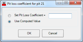
| Downstream Pit Loss Coefficient | Drainage Networks - Displays the calculated pit loss coefficient into the downstream pit. Uses both Missouri and Hare's formulae for calculating the loss. | ||||||||||
| Downstream Pit Loss Coefficient Override | Click on this icon to set a pit loss coefficient override. This override will be used instead of the automatically calculated Downstream Pit Loss Coefficient. Details of the form are as follows:
|
||||||||||