Details of the form are as follows: |
| |
|
Ribbon
Tabs (top) |
| |
Left
Click Contextual Ribbon Tab |
 |
| |
|
Left click
on a design IP to open this tab. This is direct edit
functionality for the selected IP. |
| |
Details
Panel |
|
 |
IP
Number |
IP identification |
|
Chainage |
Type in a change to
the chainage. Click Apply button to
apply the change. |
|
Level
(Elevation) |
Type in an elevation
for the IP. Click Apply button to
apply the change.
Use the arrow toggles to move the IP up/down by the set Increment
Amount. This change is immediate upon clicking
the up or down arrow shown. |
|
VC
Length |
Type in a vertical
curve length. Click Apply button to
apply the change. |
|
In
Grade (%) |
Type in an incoming
grade to the IP. Click Apply button
to apply the change. |
|
Out
Grade (%) |
Type in an outgoing
grade from the IP. Click Apply button
to apply the change. |
| |
Tools
Panel |
|
|
Increment
Amount |
Amount to raise/lower
IP's when the up/down arrow located immediately right of the Level
is pressed. |
|
 Move to IP Reference elevation Move to IP Reference elevation |
Click to move the IP
elevation to match the surface/constraint referred to in the Home
ribbon tab (IP Reference) |
|
 Delete IP Delete IP |
Click to delete the
highlighted IP. |
| |
Volumes
Panel |
Displays
the summary volume informaiton, updated as the IP is moved using
the IP Editor tools. Turn off Auto Update in
the Model Tab to disable automatic updating of
the volume information. |
|
Total
Cut |
Displays summary of
cut for the string |
|
Total
Fill |
Displays summary of
fill for the string |
|
Net |
Net summary volume |
|
Stripping |
Displays strip depth
volume (as assigned in the Design
Data Form) |
|
Pavement |
Total pavement material
volume |
|
Auto
Update Volumes |
Tick on to update the
summary volume information when the up/down level (elevation)
increment is selected or the Apply button is
pressed.
Tick off to not update the volume summary data when edits are made. |
|
 Apply Apply |
Apply edits to the
IP |
|
 Close Close |
Close this ribbon tab.
|
| |
Home
Ribbon Tab |
 |
| |
Design
Panel |
|
|
 Add IP
 |
Adds an IP (PVI) to the
Design Vertical Grading (Long Section/Profile).
Upon starting the command the Vertical Grading Editor
prompt will display Click to Insert New IP. Use the
mouse pointer to graphically select a location in the Vertical
Grading Design Window. The following form is
displayed:
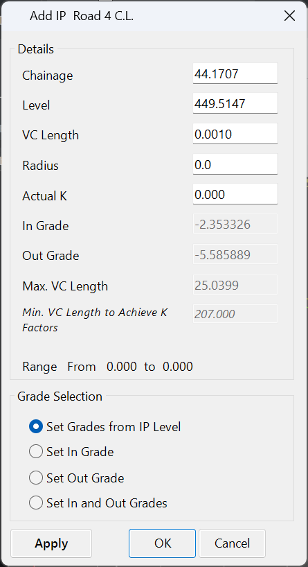 |
| Chainage
|
Type
in the chainage where the IP is required (the chainage
is adopted from the Civil 3D Alignment Stations). Note:
editable subject to the Grade Selection being
applied |
| Level |
Type
in the level (elevation) required (editable subject to
the Grade Selection being applied) |
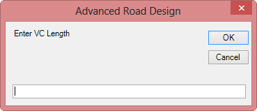
| VC
Length |
Type
in the length of vertical curve required |
| Radius |
Type
in a Radius as an alternative to the VC Length |
| In
Grade |
Type
in the grade required on the incoming tangent to the IP
(editable subject to the Grade Selection being
applied) - measured as % grade |
| Out
Grade |
Type
in the grade required on the outgoing tangent from the
IP (editable subject to the Grade Selection being
applied) - measured as % grade |
| Max.
VC Length |
This
is a reporting field identifying the maximum vertical
curve that could be applied to the IP (based on the selected
chainage) without overlapping another Vertical Curve or
IP |
| Min.
VC Length to Achieve K Factors |
This
is a reporting field identifying the minimum Vertical
Curve length that should be applied to achieve minimum
K factors.
Note: The K factors are controlled from the
Display Set
Parameters form. |
| Range
From |
Displays
the Chainage range between two IP's within which an IP
could be located without overlapping any Vertical Curve/s |
| Grade Selection |
Designers can establish the chainage
and level of the IP by specifying grade controls into
and/or out of the IP. Inputs will be adjusted
to suit the grade method specified |
| Set
Grades from IP Level |
Default
method. IP is defined by the Chainage and Level
assigned. The In Grade and Out Grade
parameters are disabled. |
| Set
In Grade |
The
IP level is defined by the incoming grade. The
In Grade is enabled. The Level
parameter is distabled. |
| Set
Out Grade |
The
IP level is defined by the outgoing grade. The
Out Grade is enabled. The Level
parameter is distabled. |
| Set
In and Out Grade |
The
IP level and chainage is defined by specifying both an
incoming and outgoing grade for the IP. The
In Grade and Out Grade parameters are enabled. The
Chainage and Level parameters are disabled. |
| OK |
Create/Edit
the IP and exit the form. |
| Cancel |
Exit
the form without creating/editing the IP. |
| Apply |
Create/Edit
the IP without exiting the form. |
|
|
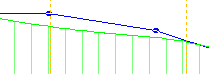
 Snap
IP to 'Snap to' Constraint at Cross Section
Snap
IP to 'Snap to' Constraint at Cross Section |
Creates an IP at a
cross section nearest the selected location, with the level (elevation)
being adopted from the surface or Design Constraint as shown in
the Snap To field (by default, this
is the sampled (existing) surface).
Upon starting the command the Vertical Grading Editor prompt
will display Select Point on <Snap To>. Use
the mouse pointer to locate the nearest cross section where the
IP is required. An IP will be created with levels applied
based on the surface/constraint shown in the Snap To field,
with a VC length of .001m.
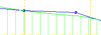
Example shown, below:
Command Started - Select Location
 |
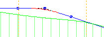
|
Command Complete - New IP at
Chainage
 |
|
|
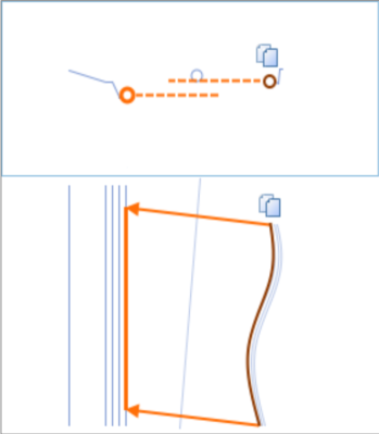
 Snap IP to 'Snap To' Constraint
 |
Creates an IP with
the chainage adopted from the location selected by the user and
with the level (elevation) being adopted from the surface or Design
Constraint as shown in the Snap To field (by default, this
is the sampled (existing) surface).
Upon starting the command the Vertical Grading Editor prompt
will display Select Chainage on <Snap To>. Use
the mouse pointer to locate the chainage where the IP is required. An
IP will be created with levels applied based on the surface/constraint
shown in the Snap To field, with a VC length of .001m.
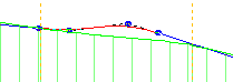
Example shown, below:
Command Started - Select Location
 |
|
Command Complete - New IP at
Select Location
 |
|
|
Delete IP |
Deletes
an IP (PVI) from the Design Vertical Grading (Long Section/Profile).
Upon starting the command the Vertical Grading Editor prompt
will display Click on IP to Delete. Use the mouse
pointer to graphically select an IP in the Vertical Grading
Design Window. The selected IP will be deleted
from the design. A new tangent will be created between
the two adjoining IP's to form a continuous long section. |
|
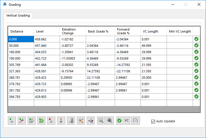
 Grid Editor Grid Editor |
|
| Grid View |
Displays the vertical design in
a grid view. As each item is clicked on a marker
is displayed in plan at the vertical IP location. List
items are described below
NOTE: Typing into the blank Distance cell at the
bottom of the list and movign to another cell will create
a new IP at that distance. |
| Distance |
Chainage
along string for IP location |
| Level |
Elevation
of the IP |
| Elevation
Change |
Elevation
difference from the current IP to next IP |
| Back
Grade % |
Grade
from the current IP to the previous IP |
| Forward
Grade % |
Grade
from the current IP to the next IP |
| VC Length |
Type in a vertical curve length to apply
at the IP. Leave at .001 for no Vertical Curve
to be applied |
| Min VC Length |
This column provides feedback on the required
Vertical Curve length to achieve minimum sight distance
along the string centreline. Users must first
establish  speed criteria. speed criteria.
|
| Icon (compliant/non-compliant) |
Tick or cross icon to highlight whether
the curve provides suffiicient sight distance or not. |
 Add IP by selection Add IP by selection |
Pick
a location in the drawing along the grading string - an
IP will be added at that location |
 Add IP by
Reference Add IP by
Reference |
Adds
a vertical IP from a reference point selected in the drawing.
At the command prompt, select a location in the drawing
to use as a REFERENCE point for elevations to a new IP.
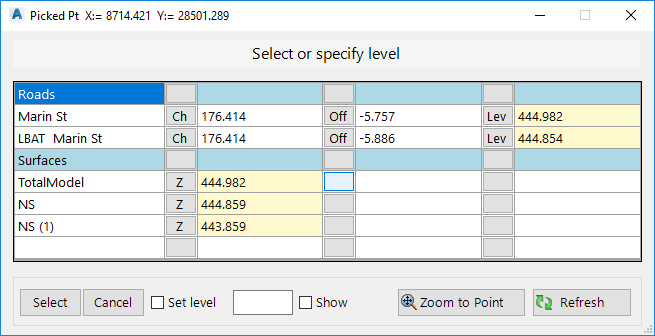
The following form will display:
|
| List View of Elevations
at the location selected. |
| Objects
Found |
Lists
Surfaces and Strings located in proximity to the
selected point |
| Chainage/Station,
Offset, Elevation |
Other
columns describe the information type (Ch for
chainage/station, Off for offset from alignment,
Lev for level/elevation, z for surface elevation).
Users must select an elevation to apply (highlighted
with a yellow background) |
| Select |
Apply
the selected elevation to the x,y position selected. This
sets the Reference Point x,y,z position |
| Cancel |
Exit
the command without creating a new IP |
| Set
Level |
Tick
on to override the elevation to a user specified
value. Type in a value in the cell
provided |
| Show |
Tick
on to draw text for the elevation of the Reference
Point |
| Zoom
to Point |
Zoom
to the selected x,y point
|
| Refresh |
Refresh
enquiry tool and drawing display |
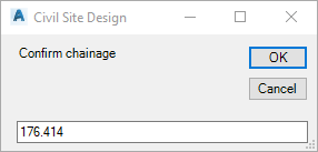
Upon clicking Select, the user is prompted ('Pick point
on String for new elevation) to graphically locate the
location along the string C.L. to create the new IP. Upon
selection the following form displays:
|
| Chainage/Station |
Confirm
the location along the string to create the new
IP. Overtype as required |
| OK |
Proceed
to next step |
| Cancel |
Cancel
the command |
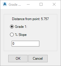
Upon clicking OK, the user is prompted to select a grade/slope
to apply from the REFERENCE Point to the selected location
on the string.
|
| Grade
1: or % Slope |
Toggle
to select the method for setting the final elevation
of the IP. Input the value required
(note: a Grade of 1:0 is not allowed) |
| OK |
Create
a new IP |
| Cancel |
Cancel
the command |
|
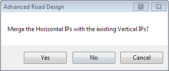
 Add IP's at horizontal geometry Add IP's at horizontal geometry |
Adds
vertical IP's at horizontal geometry points along the
polyline. The following form will display:
|
| Yes |
Adds
extra IP's at the horizontal geometry points,
keeping the existing design IP's |
| No |
Replaces
the current vertical design with IP's only at
the horizontal geometry points. |
| Cancel |
Do
not add IP's at horizontal geometry points |
|
 Add IP's to Match Surface Levels
at Selected Sections Add IP's to Match Surface Levels
at Selected Sections |
Creates
IP's at all sampled sections around the grading string
and sets the elevation of the IP's to match the surface |
 Delete IP Delete IP |
Deletes
the first highlighted IP in the grid view |
 Raise/Lower All IP's Raise/Lower All IP's |
Raises/Lowers
all IP's by a user defined amount. Inputs are
as follows:
|
| Input |
Type
in an elevation change (positive up, negative
down) |
| OK |
Apply
elevation change |
| Cancel |
Do
not apply and exit form |
|
 Edit Multiple IP's Edit Multiple IP's |
Select
multiple rows in a column to edit that column. Options
are:
| Level column
cells are highlighted |
|
| Input |
Type
in an elevation change (positive up, negative
down) to apply to all highlighted cells |
| OK |
Apply
elevation change |
| Cancel |
Do
not apply and exit form |
| Grade % cells
are highlighted |
|
| Input |
Type
in a single grade (%) to apply to all highlighted
cells |
| OK |
Apply
grade (%) change |
| Cancel |
Do
not apply and exit form |
| VC
Length column cells
are highlighted |
|
| Input |
Type
in a VC length to apply to all highlighted cells. VC
length will be truncated to prevent overlapping
IP's or other VC's as required. |
| OK |
Apply
elevation change |
| Cancel |
Do
not apply and exit form |
|
 Edit by Reference
 |
This
is an EDIT command. Before running this command,
users must first highlight the IP to edit, then select
this command.
At the command prompt, select a location in the drawing
to use as a REFERENCE point for elevations to the selected
IP. A graphic line shows the position of the
current IP and the mouse location of the reference point. Click
to select the reference point location.
The following form will display:
|
| List View of Elevations
at the location selected. |
| Objects
Found |
Lists
Surfaces and Strings located in proximity to the
selected point |
| Chainage/Station,
Offset, Elevation |
Other
columns describe the information type (Ch for
chainage/station, Off for offset from alignment,
Lev for level/elevation, z for surface elevation).
Users must select an elevation to apply (highlighted
with a yellow background) |
| Select |
Apply
the selected elevation to the x,y position selected. This
sets the Reference Point x,y,z position |
| Cancel |
Exit
the command without creating a new IP |
| Set
Level |
Tick
on to override the elevation to a user specified
value. Type in a value in the cell
provided |
| Show |
Tick
on to draw text for the elevation of the Reference
Point |
| Zoom
to Point |
Zoom
to the selected x,y point
|
| Refresh |
Refresh
enquiry tool and drawing display |
Upon clicking Select, the user is prompted ('Pick point
on String for new elevation) to graphically locate the
location along the string C.L. to create the new IP. Upon
selection the following form displays:

|
| Chainage/Station |
Confirm
the location along the string to create the new
IP. Overtype as required |
| OK |
Proceed
to next step |
| Cancel |
Cancel
the command |
|
| Grade
1: or % Slope |
Toggle
to select the method for setting the final elevation
of the IP. Input the value required
(note: a Grade of 1:0 is not allowed) |
| OK |
Update
the IP elevations |
| Cancel |
Cancel
the command |
|
 Increment Chainages Increment Chainages |
Increments
all Chainages/Stations/Distances for highlighted rows. Type
in an increment and the selected IP's will be shifted
by the set amount.
A warning message will display if the shift will result
in IP's overlapping any vertical curves or other IP's
and the edit will not be applied.
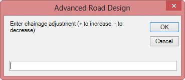
|
| Input |
Type
in an increment (+ or -) to adjust the chainage/station
of the highlighted IP's. |
| OK |
Apply
increment to chianages/stations. |
| Cancel |
Do
not apply and exit form |
|
 Zoom IP Zoom IP |
Zooms
to the selected IP in the drawing |
 Zoom All Zoom All |
Zooms
to the extents of the grading string |
 Fix VC
 |
This
will increase the size of all vertical curves to achieve
the minimum sight distance requirement, where the current
vertical curve length is inadequate. |
 Speed Tables Speed Tables |
Opens
the Speed Table
form to establish sight
distance criteria to check.
Special Note: Once speed based design
criteria have been applied, any non-compliant vertical
curves will be drawn in RED
in the graphical area
|
| Auto
Update |
If
ticked on, the Vertical Grading Editor and associated
surface/s will update as changes are applied in the grid
view.
If unticked, making a change in the grid editor will display
this button  . Click
to update models. . Click
to update models.
|
|
| |
Editing
Panel |
|
|
 Automate Vertical Design
 |
This command provides
access to a variety of calculation methods to generate a vertical
grading for the current CSD Object open in the Vertical Grading
Editor.
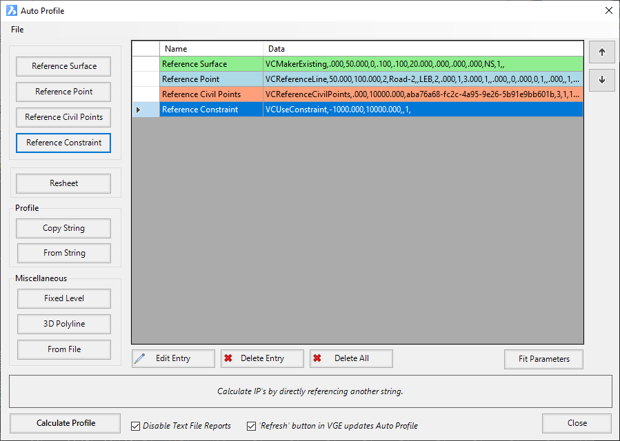
As VC Methods are applied they are added to the list. The
Vertical Grading controls are applied in order, from the
top to bottom of the list. The list can be
reordered using the up/down arrows on the right.
|
| File
Menu |
Command
buttons enable the user to select the method desired for
setting the vertical grading |
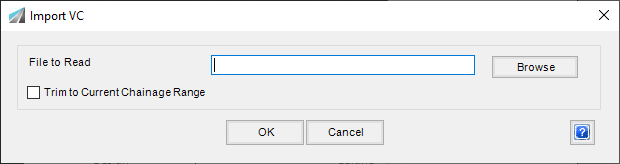
| Import CSD Vertical
Design |
The Import
VC command allows the designer to import a vertical
grading design to file. The file structure matches what
is created when Export VC is used. It
would be usual to use Export VC to create
an exported vertical curve file, edit in a program such
as Notedpad, then use this command to import the changed
vertical design back in.
|
| Export CSD
Vertical Design |
The Export VC command allows the
designer to export a vertical grading design to file.
The file exported can be opened in a program such as Notepad
to be edited. A window will display to select a save location
and a name for the export file. |
| |
Calculate
centreline elevations using the following methods |
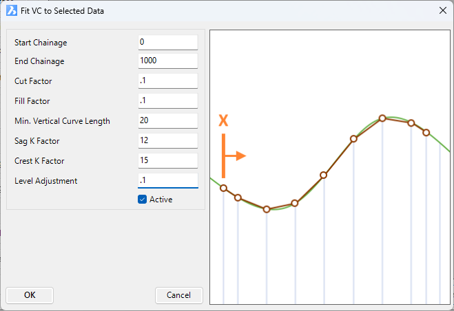
| Reference
Surface |
This method
allows the designer to create IP's at sampled sections
(over a specified chainage range) and match the elevations
of these IP's to a specified surface model. If the Use
Fitting option is checked, the software will filter
out the calculated IP's and smooth the design by inserting
vertical curves. This option can also be used to add a
level adjustment. For example, the designer might opt
to match all levels to an existing surface and then raise
this design by 50mm.

|
| Start
Chainage |
Apply
from start chainage |
| End
Chainage |
Apply
to end chainage |
| Surface |
Pick
list for surface to extract levels from |
| Use
Fitting |
Toggle
this on to 'smooth' out the design. The software
will apply a cut and fill factor to create an envelope
of levels, then fit IP's so the tangents do not pass
outside the envelope. |
| Cut
Factor |
Allows
for this amount of cut against the sampled surface
before inserting a new IP |
| Fill
Factor |
Allows
for this amount of fill against the sampled surface
before inserting a new IP |
| Min.
Vertical Curve Length |
Sets
the minimum desired vertical curve length |
| Sag
K Factor |
Vertical
curve lengths will be set from this K factor in
sag situations, where possible |
| Crest
K Factor |
Vertical
curve lengths will be set from this K factor in
crest situations, where possible |
| Level
Adjustment |
Lifts/lowers
the outputted fitted vertical grading |
| Active |
Untick
to disable the entry |
| OK |
Apply
and exit. |
| Cancel |
Exit
the form without changing any data. |
|
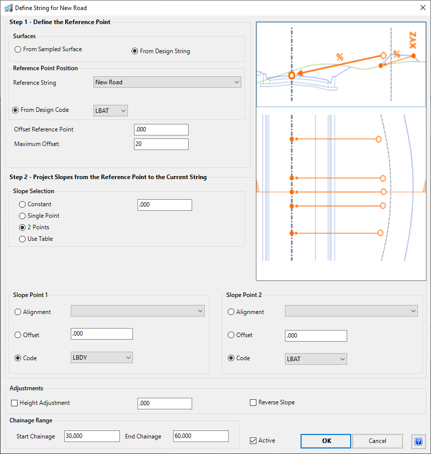
| Reference
Point |
This method
will create IP's at each sampled section based on selecting
a Reference Point and slope projection to the current
Vertical Grading. This is the most versatile
option for establishing levels based on existing or design
data.
There are three Steps in the process:
- Define the Reference
Point: The Reference Point is used as a reference
for levels and offsets to the current Vertical Grading. Designers
select to extract levels from either the Design surface
or the Sampled Surface, then select the method to
determine the offsets. Offset and levels
provide the Reference Point
- Project Slopes from
the Reference Point to the Current String: Designers
are able to have the software calculate slopes from
the Reference Point to the current Vertical
Grading based on a variety of different methods
- Apply Slope and Level
Adjustments: Users can elect to add a height adjustment
to the calculated levels and/or use the reverse of
the calculated slopes obtained from Step 2
The calculations of the Reference Point and Projected
Slopes is made at EACH sampled section and an IP level
established (with an optional height adjustment).
The image on the right side of the form adjusts to highlight
relevant inputs based on the mouse hover location on the
form.
Details of the Form and the steps are as follows:
|
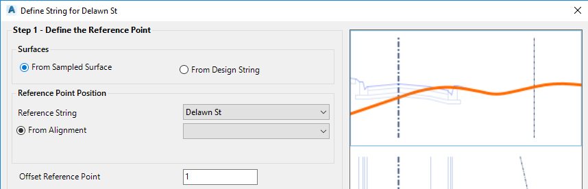
Step 1 - Define the
Reference Point |
| Surfaces |
Obtain
Levels for Reference Point and Slope from
- options are to use the Sampled Surface or Design |
| From Sampled
Surface |
Toggle
- Levels are read from the Sampled surface in
calculating the reference point and slopes (pending
slope option used). Form display is
as follows:
|
| From Design
Surface |
Toggle
- Levels are read from either a design String
or Code in calculating the reference point and
slopes (pending slope option used). Form
display is as follows:

|
| Reference
Point Position |
Sets
the offset at which to calculate the Reference
Point - elevation is then calculated from the
sampled or design surface, based on selected toggle
option |
| Reference String |
Use
the pick list to select the Reference String. Behaviour
is as follows:
- From Sampled Surfaces selected. This
sets the new IP locations (by chainage/station)
on the current string CL. It would
be usual to select the current design C.L. string.
- Drom Design String selected. This
sets the design surface from which to extract
elevations (as well as setting the new IP locations
(by chainage/station) ont the current string C.L.). |
| From
Alignment |
Select
an alignment for the offset location of the Reference
Point.
Only available if From Sampled Surfaces
is selected. |
| From
Design Code |
Select
a Code for from the Reference String to use for
the offset location of the Reference Point.
Only available if From Design String
is selected. |
| Offset Reference Point |
User
can 'shuffle' the Reference Point offset using
this option - type in the required value (-ve
for Left and +ve for Right) |
| Maximum Offset |
Set
a maximum offset to search for the Reference Point,
measured from the alignment/string centreline
|
Step 2 - Project
Slopes from the Reference Point to the Current
String |
| Slope
Selection |
Toggles
to select the method of calculating the slope
projections from the Reference Point. The
form display provides different inputs depending
on the toggle option selected. |
| Constant |
Allows
for the specification of a single crossfall to
apply from the Reference Point to obtain levels.
Hover over the Constant option to review the
behaviour.
User input is as follows:
| Constant |
Type
in the % slope project required |
|
| Single Point |
Calculates
the Slope at a selected offset and uses the calculated
slope to obtain levels.
Hover over the Constant option to review the
behaviour.
User input is as follows:
| |
Slope Point
1 - Obtain Offset/Slope from:
Use the Toggle to select the required
method |
| Alignment |
Use
the pick list to select an alignment to
determine the offset location to calculate
the slope |
| Offset |
Behaviour
is subject ot the Surfaces option selected:
- From Sampled Surface selected.
Type in a fixed offset from the string
C.L. Alignment. Convention
is -ve left of the C.L. and +ve right
of the C.L.
- From Design String selected.
Type in a fixed offset from the Reference
String. Convention is -ve left
of the C.L. and +ve right of the C.L. |
|
| 2 Points |
Calculates
the Slope between two selected offsets and uses
the calculated slope between the two points to
obtain levels.
Hover over the Constant option to review the
behaviour.
The average slope is calculated between the
offset/level found for the two Slope Points and
is then applied.
User input is as follows:
| |
Slope Point
1 - Obtain Offset/Slope from:
This records the first offset value and
then sets the level based on the Sampled
Surface or Design Surface. Use
the Toggle to select the required method |
| Alignment |
Use
the pick list to select an alignment to
determine the offset location |
| Offset |
Behaviour
is subject ot the Surfaces option selected:
- From Sampled Surface selected.
Type in a fixed offset from the string
C.L. Alignment. Convention
is -ve left of the C.L. and +ve right
of the C.L.
- From Design String selected.
Type in a fixed offset from the Reference
String. Convention is -ve left
of the C.L. and +ve right of the C.L. |
| |
|
| |
Slope Point
2 - Obtain Offset from: This records
the second offset value and then sets
the level based on the Sampled Surface
or Design Surface. Use the
Toggle to select the required method |
| Alignment |
Use
the pick list to select an alignment to
determine the offset location |
| Offset |
Behaviour
is subject ot the Surfaces option selected:
- From Sampled Surface selected.
Type in a fixed offset from the string
C.L. Alignment. Convention
is -ve left of the C.L. and +ve right
of the C.L.
- From Design String selected.
Type in a fixed offset from the Reference
String. Convention is -ve left
of the C.L. and +ve right of the C.L. |
|
| Use Table |
User
is able to set crossfall values in a table - the
software applies the selected crossfalls based
on chainage and crossfall entries in the table. Interpolation
occurs between the crossfall entries in the table.
Hover over the Constant option to review the
behaviour.
User input is as follows:
| |
Table:
inputs are as follows |
| Chainage |
Type
in a chainage |
| Specified Crossfall
% |
Type
in a crossfall value |
| |
Note:
the software will interpolate crossfall
values between the chainages in the table |
| Sort |
Sorts
the chainage values in the table from
lowest to highest, using the Start Chainage
column. |
|
Step 3 -
Apply Slope and Level Adjustments |
| Adjustments |
Raise/lower
the calculated elevation or reverse slope for
calculation |
| Height
Adjustment |
Toggle
ON if a height adjustment should be added to the
calculated levels.
Type in a value to raise/lower (+ raises the
IP's) the calculated levels. |
| Reverse
Slope |
Toggle
ON to reverse the calculated/defined slope values
and apply this to determine the calculated levels. |
| Chainage
Range |
|
| Start Chainage |
Apply
from start chainage |
| End Chainage |
Apply
to end chainage |
| Active |
Untick
to deactivate (not apply) the control. |
| OK |
Apply
the inputs and exit the form |
| Cancel |
Exit
without applying changes |
|
| Reference
Civil Points |
Click on
this option to create IPs from Civil Points.
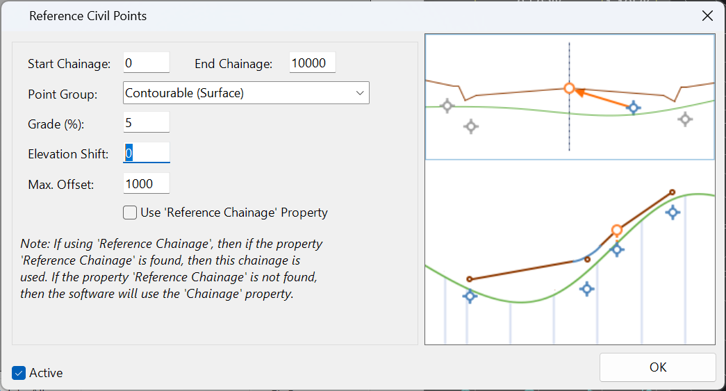
User input is as follows:
| Start Chainage |
Apply
from start chainage |
| End Chainage |
Apply
to end chainage |
| Point
Group |
Select
a Point Group containing Civil Points. |
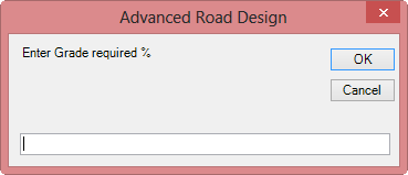
| Grade
(%) |
Using
the elevation of the Civil Point, apply the specified
Grade to calculate the IP elevation. |
| Elevation
Shift |
Type
in an elevation change to apply to the calculated
Civil Point elevation. |
| Max.
Offset |
Type
in a maximum offset (measured perpendicular to
the current String) to search for Civil Points
to apply. |
| Active |
Untick
to deactivate (not apply) the control. |
| OK |
Apply
the inputs and exit the form |
|
| Reference
Constraint |
Click on
this option to create IPs at a constraint as defined in
the design data form. Form displays as follows:
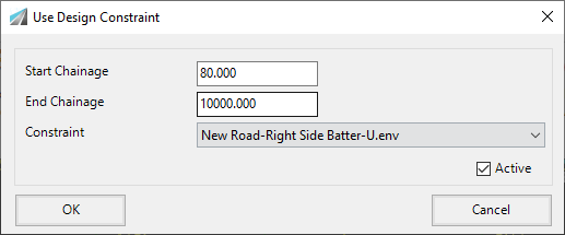
User input is as follows:
| Start Chainage |
Apply
from start chainage |
| End Chainage |
Apply
to end chainage |
| Constraint |
Choose
a constraint that has been defined in the Design
Constraints section of the Design Data form |
| Active |
Untick
to deactivate (not apply) the control. |
| OK |
Apply
the inputs and exit the form |
| Cancel |
Exit
without applying changes |
|
| Resheet |
Click on
this option to set the road centreline levels to acheive
a minimum overlay depth for resheeting. Form
displays as follows:
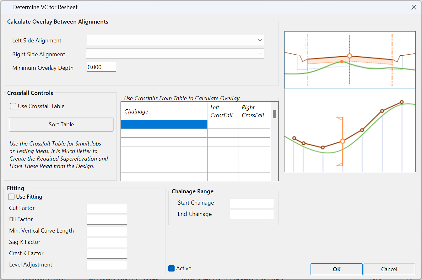
User input is as follows:
|
| Left
Side Alignment |
Select
left side alignment |
| Right
Side Alignment |
Select
right side alignment |
| Minimum
Overlay Depth |
Sets
the minimum thickness for overlay |
| Use
Crossfall Tables |
If
ticked command will use the crossfall tables rather
than the alignments |
| Crossfall
Table |
input
values for chainage and crossfall to be used to
calculate the overlay / resheeting depths |
| Use
Fitting |
Toggle
this on to 'smooth' out the design |
| Cut
Factor |
Allows
for this amount of cut against the sampled surface
before inserting a new IP |
| Fill
Factor |
Allows
for this amount of fill against the sampled surface
before inserting a new IP |
| Min.
Vertical Curve Length |
Sets
the minimum desired vertical curve length |
| Sag
K Factor |
Vertical
curve lengths will be set from this K factor in
sag situations, where possible |
| Crest
K Factor |
Vertical
curve lengths will be set from this K factor in
crest situations, where possible |
| Level
Adjustment |
Lifts/lowers
the outputted fitted vertical grading |
| Start Chainage |
Apply
from start chainage |
| End Chainage |
Apply
to end chainage |
| Active |
Untick
to deactivate (not apply) the control. |
| OK |
Apply
and exit. |
| Cancel |
Exit
the form without changing any data. |
|
| Profile |
Copies
the vertical geometry from another String |
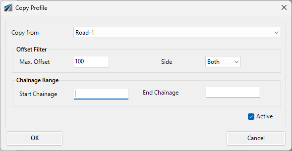
| Copy
String |
This method
allows the current vertical grading to be created using
the vertical grading of an existing string. All the IP's
(chainage and level data) on the existing string will
be re-created in the current vertical grading.
|
| Copy
from |
Select
the String/Profile to copy the vertical design
from |
|
Offset Filter |
Set how far to search and which side to find string data |
|
Max Offset |
maximum search offset from the current String to find
the Copy from String |
|
Side |
Search Left, Right or Both sides. |
|
Chainage Range |
|
| Start
Chainage |
Apply
from start chainage |
| End
Chainage |
Apply
to end chainage |
| Active |
Untick
to deactivate (not apply) the control. |
| OK |
Apply
and exit. |
| Cancel |
Exit
the form without changing any data. |
|
| From
String |
Click on
this option to copy another String/Profile, with the capacity
to adjust the IP levels based on grade or elevation controls.
This routine was originally envisaged for road reconstruction
works, where it was desired to take the design for one
side of the road and project it across to the other side. The
copied profile IP's and Vertical Curves are transferred
to the current Vertical Grading.
At least one other string must be available in the drawing.
Form display is (be default) as follows:
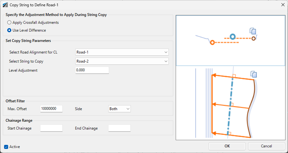
Under the heading Specify the Adjustment
Method to Apply During String Copy select
one of two calculation methods:
- Apply Crossfall Adjustments
- Use Level Difference
The graphic and inputs will adjust depending
on the option selected.
User input is as follows:
|
| |
Apply Crossfall Adjustments:
the original profile data is copied across, with
the IP levels adjusted based on crossfalls from
a selected profile to the current Vertical Grading
 |
| Select String to Copy |
Use
the pick list to select the profile to copy data
from |
| Select Road Alignment
for CL |
Use
the pick list to select a Road centreline |
| Crossfall to CL |
Type
in a crossfall to adjust levels of the IP's to
the CL |
| Crossfall to Current
String |
Type
in a crossfall from the CL to the current Vertical
Grading |
|
Offset Filter |
Set how far to search and which side to find string data |
|
Max Offset |
maximum search offset from Road Alignment for CL to find
String to Copy |
|
Side |
Search Left, Right or Both sides. |
|
Chainage Range |
|
| Start
Chainage |
Apply
from start chainage |
| End
Chainage |
Apply
to end chainage |
| Active |
Untick
to deactivate (not apply) the control. |
| OK |
Apply
and exit. |
| Cancel |
Exit
the form without changing any data. |
| |
|
| |
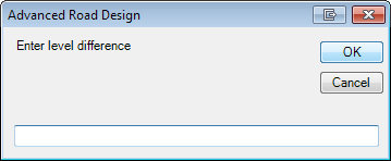
Use Level Difference:
the original profile data is copied across, with
the IP levels adjusted by a fixed height change |
| |
 |
| Select String to Copy |
Use
the pick list to select the profile to copy data
from |
| Select Road Alignment
for CL |
Use
the pick list to select a Road centreline |
| Level Adjustment |
Type
in a value to adjust the levels of the IP's copied
to the current Vertical Grading |
| Start Chainage |
Apply
from start chainage |
| End Chainage |
Apply
to end chainage |
| Active |
Untick
to deactivate (not apply) the control. |
| OK |
Apply
the profile copy to the current Vertical Grading |
| Cancel |
Exit
without applying vertical grading changes |
|
| Miscellaneous |
List
of miscellaneous methods for establishing the string elevations |
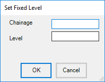
| Fixed
Level |
Click on
this option to create IP's at each sampled section and
assign them all the same elevation. Form displays
as follows:
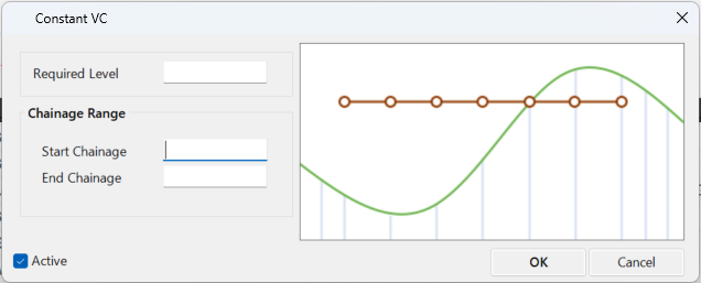
User input is as follows:
|
| Required
Level |
Type
in the desired level |
| Start
Chainage |
Apply
from start chainage |
| End
Chainage |
Apply
to end chainage |
| Active |
Untick
to deactivate (not apply) the control. |
| OK |
Apply
and exit. |
| Cancel |
Exit
the form without changing any data. |
|
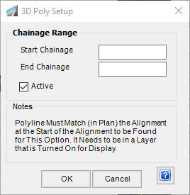
| 3D
Polyline |
Click on
this option to check for a 3D polyline co-incident with
the alignment and read the 3D levels into the Vertical
Grading.
This is automatic - if a 3D polyline is not found an
error message will display 'Unable to locate 3D polyline
matching alignment <Alignment Name>'
|
| Start
Chainage |
Apply
from start chainage |
| End
Chainage |
Apply
to end chainage |
| Active |
Untick
to deactivate (not apply) the control. |
| OK |
Apply
and exit. |
| Cancel |
Exit
the form without changing any data. |
|
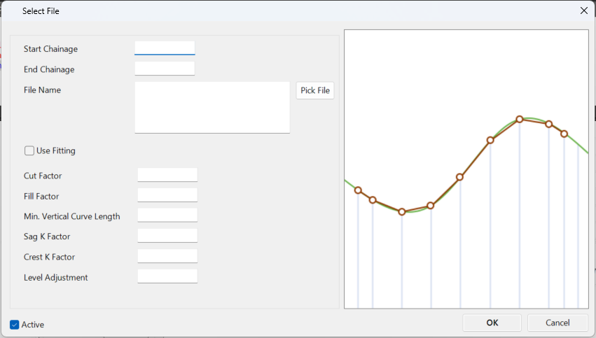
| From
File
|
The From
File command allows the designer to import a file
of vertical geometry points and create IP's and vertical
curves from this data. as well as fitting the data during
import.
The expected file format is as follows (editable in a text
editor) and matches the format of the file used in the
Export VC command. However,
this command will allow import of ONLY a file with extension
.txt.
<Chainage>,<Elevation>,<Vertical Curve
Length> separated by an [Enter] per point. Save
the file with extension .txt.
Example file:
0, 110
60, 95,80
120, 93
|
| [List
View] |
List
of each entry used to calculate centreline elevations |
| Name |
Name of
entry type |
| Data |
Summary
of data inputs |
| Edit
Entry |
Edits the
highlighted entry in the list |
| Delete
Entry |
Deletes
the highlighted entry in the list |
| Delete
All |
Deletes
all entries in the list |
| Fit
Parameters |
Although
some methods, such as the Match to Existing method
contain Fitting parameters, this method allows for an
overall Fit/Smooth to be applied over a calculated vertical
design. A calculated design might consist of a combination
of multiple methods and these Fit Parameters can
be added as the final method to be applied. Alternatively,
this method can only be applied when the Fitting
command is used.
|
| Start
Chainage |
Apply
from start chainage |
| End
Chainage |
Apply
to end chainage |
| Cut
Factor |
Allows
for this amount of cut against the sampled surface
before inserting a new IP |
| Fill
Factor |
Allows
for this amount of fill against the sampled surface
before inserting a new IP |
| Min.
Vertical Curve Length |
Sets
the minimum desired vertical curve length |
| Sag
K Factor |
Vertical
curve lengths will be set from this K factor in
sag situations, where possible |
| Crest
K Factor |
Vertical
curve lengths will be set from this K factor in
crest situations, where possible |
| Level
Adjustment |
Lifts/lowers
the outputted fitted vertical grading |
| OK |
Apply
and exit. |
| Cancel |
Exit
the form without deleting any data. |
|
 Move Up Move Up |
Moves the
selected entry up in the list. |
 Move Down Move Down |
Moves the
selected entry down in the list. |
| Information
Panel |
Non-editable
information panel describing command inputs as the mouse
is hovered over each button. |
| Calculate
Profile |
Calculate
new design IP positions as per the inputs. |
| Disable
Text File Reports |
A text file
is created and displayed, detailing the calculation
results. Tick this option to disable the text
file creation. |
|
'Refresh' button in VGE updated Auto Profile |
Defaults as
ticked on. When ticked on, clicking on the Sync/Refresh
button in the Vertical Grading Editor window will automatically
re-apply the Auto Profile actions. |
|
Close |
Close the form |
|
|
 Edit IP
 |
Numerically edit an
IP by selecting it in the drawing.
Upon starting the command the Vertical Grading Editor prompt
will display Click on IP to Edit. Use
the mouse pointer to graphically select an IP in the Vertical
Grading Design Window.
Note: Except for the title of the form, the design
inputs exactly match the  Create IP command. Please
refer above for more details on these
inputs Create IP command. Please
refer above for more details on these
inputs |
|
 Move
IP Anywhere Move
IP Anywhere |
Graphically move an
IP anywhere within the limits of the constraining vertical curves
or other IPs.
Upon starting the command the Vertical Grading Editor prompt
will display Click on IP to Move. Click on
or near an IP to select it for relocation. After selecting
an IP it can be moved using the mouse. Click to store
the new IP location. |
|
 Move
IP Up/Down by Mouse Move
IP Up/Down by Mouse |
Graphically move an
IP up or down whilst constraining movement along the chainage.
Upon starting the command the Vertical Grading Editor prompt
will display Click on IP to Move. Click on
or near an IP to select it for relocation. After selecting
an IP it can be moved using the mouse. Click to store
the new IP location. |
|
 Add
to all IP Levels Add
to all IP Levels |
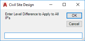 |
| Enter
elevation change |
Type
in the amount to raise/lower all IP's by |
| OK |
Exit the
form and raise/lower all IP's by the change value |
| Cancel |
Exit
the form without editing the IP's |
|
|
 Edit
IP's over a range Edit
IP's over a range |
Click here to open
and focus on a new Ribbon Tab for editing of a group of IP's in
a design:
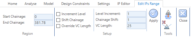 |
| Region
tab |
Define
the region over which to edit IP's. |
| Start
Chainage |
Start
chainage to define a chainage range for editing IP's. |
| End
Chainage |
Start
chainage to define a chainage range for editing IP's. |
| Setup
tab |
Establish
what to change and by how much |
| Increment
Level (Elevation) |
Tick
on to apply a relative elevation change to the group |
| Level
Increment |
Type
a value for relative elevation change |
| Shift
Chainage |
Tick
on to apply a lateral move of the group. |
| Chainage
Shift |
Type
a value for the lateral move |
| Override
VC Length |
Tick
on to apply a vertical curve length to all IP's in the
group |
| VC
Length |
Type
in a vertical curve length |
|
Apply |
Click
to apply selected changes to the group. |
| Move to IP Reference elevation |
Click to
move the IP elevation to match the surface/constraint
referred to in the Home ribbon tab (IP
Reference) |
| Delete IP |
Click to
delete the highlighted IP. |
| Close |
Close this
ribbon tab. |
|
|
 Slide
IP on Grade Slide
IP on Grade |
Graphically slide an
IP along an incoming or outgoing grade.
Upon starting the command the Vertical Grading Editor prompt
will display Click on IP to Slide. Click immediately
to the left of an IP to hold the grade left of the IP. Click
immediately to the right of an IP to hold the grade right of the
IP. Use the mouse to set the new position of the IP. Click
to store the new IP location. |
|
 Move
IP Left/Right Move
IP Left/Right |
Graphically move a
selected IP left/right and constrain any vertical movement.
Upon starting the command the Vertical Grading Editor prompt
will display Click on IP to Move. Click on or near an IP
to select it and use the mouse to drag the IP left or right to
set the new position of the IP. Click to store the new IP location. |
|
 Specify
Elevation Specify
Elevation |
Edit an IP by setting
a Chainage and Level that the design vertical grading must intersect. The
selected IP will be raised/lowered so that the design vertical
grading passes through the specified chainage and level.
Upon starting the command the Vertical Grading Editor prompt
will display Select Required IP. After selecting
the IP to edit the following form is displayed:
 |
| Chainage
|
Type
in the required chainage |
| Level |
Type
in the level (elevation) required |
| OK |
Exit the
form and edit the IP level (elevation) so that the design
vertical grading passes through the specified chainage
and level |
| Cancel |
Exit
the form without editing the IP |
|
|
 Fit
Vertical Curve/s Between IP's Fit
Vertical Curve/s Between IP's |
This command is used
to insert a either a single vertical curve or a vertical curve
pair based on the incoming grade to the first IP and the outgoing
grade from the second IP. The process is the same as
is used for designing Kerb Returns and is as follows:
|
|
Raise/Lower
IP by Fixed Amount |
Move an IP up and down
by a user defined increment.
Upon starting the command the Vertical Grading Editor prompt
will display Select IP to Raise/Lower. After
selecting the IP the prompt changes to Use Up/Down. Select
Drawing to End and a scroll icon  appears. The
IP level is then changed by the value shown in the text box each
time the scroll Icon is selected. appears. The
IP level is then changed by the value shown in the text box each
time the scroll Icon is selected.
As indicated by the prompt, stop the command by clicking the
left mouse button in the graphics area.
Special
Note: If the option 'Show Volumes' is toggled on in
the  Display Set Parameters
form, then a Volume Summary window will display showing the
total earthworks and volumes. This information will
update on movement of the selected IP up or down incrementally. Display Set Parameters
form, then a Volume Summary window will display showing the
total earthworks and volumes. This information will
update on movement of the selected IP up or down incrementally. |
|
 Raise/Lower
All IP's to achieve Balanced Earthworks Raise/Lower
All IP's to achieve Balanced Earthworks |
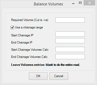
Note: Curve correction is always applied to this sectional
volume calculation. Trimming for intersections
or other network strings is not accounted for.s |
| Enter
required volume |
Type
in the required volume (cut requires '-') |
| Use
Chainage Range |
Pick
to define a chainage range to balance volumes |
| Start
Chainage IP |
Input
start chainage from which IP's can be modified when the
calculation is undertaken |
| End
Chainage IP |
Input
end chainage to which IP's can be modified when the calculation
is undertaken |
| Start
Chainage Volumes Calc |
Input
the start chainage from which the volume calculation will
start |
| End
Chainage Volumes Calc |
Input
the end chainage to which the volume calculation will
end |
| OK |
Exit the
form and raise/lower IP's to achieve the set volume |
| Cancel |
Exit
the form without editing the IP's |
|
|
 Enquire
Elevation Enquire
Elevation |
This command is used
to query the elevation at a particular chainage. Inputs are as
follows:
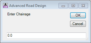 |
| Enter
Chainage |
Type
in the chainage to report the level |
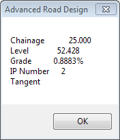
| OK |
Exit the
form and display the level details at the defined chainage. Example
output as follows:
|
| Cancel |
Exit
the form without editing the IP's |
|
|
 Undo Undo |
Undo edits in the current
section |
|
 Redo Redo |
Redo edits in the current
session |
|
 Refresh/Sync
 |
Updates intersection
match-in, reapplies the Auto Profile controls (unless disabled) and display on screen, as required. |
| |
Display
Panel |
|
|
 IP Reference
 |
Sets the item to snap
to when using the
"Snap IP to 'Snap to' Constraint at Cross Section" or
"Snap
IP to 'Snap To' Constraint" options |
|
 Exaggeration Exaggeration |
Sets the maximum scale
exaggeration of the longsection |
|
Current
Exaggeration |
Displays the current
vertical exaggeration applied |
| |
Reset
Panel |
|
|
Delete
All IP's |
Deletes all design
IP's and reinstates two IP's - one at the start and one at the
end, both adopting the elevations of the sampled surface |
| |
Common
Panel |
|
|
 Open Template Editor Open Template Editor |
Select this button
to create/edit a typical cross section template. Full
details in the Create/Edit
Section Template form. |
|
 Open Volume Report Open Volume Report |
Click on this icon
to generate a report of the volumes.

The details of this form can be found in the  Volumes
report command. The Volumes
command interface is exactly the same, except that a third panel
is also shown on the left listing all Strings for selection. Volumes
report command. The Volumes
command interface is exactly the same, except that a third panel
is also shown on the left listing all Strings for selection. |
|
 Open Design
Data Form Open Design
Data Form |
Select this button
to access the Design
Data Form. |
|
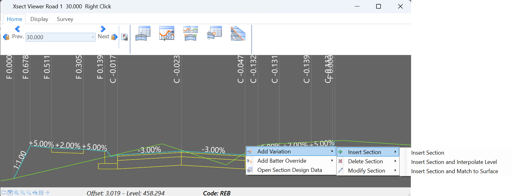
 Open Cross Section
Viewer Open Cross Section
Viewer |
Select this button
to open an instance of the Cross
Section Viewer. The designer will be prompted to select a
location in the graphical area to initially load the nearest sampled
cross section into the viewer.
|
| |
Model
Ribbon Tab |
 |
| |
Auto
Update Panel |
|
|
Auto
Update toggle |
Toggle on to automatically
update models (linework and surfaces) when changes are applied
to the string design (or cross sections) |
|
Update
Model |
If automatic update
is unticked, this will udpate the model/s in the drawing following
design changes in the Vertical Grading Editor window |
|
 String Surface String Surface |
Click to create an
CSD Surface of the CSD Object being graded. This surface
is outputted without regard to any other CSD Object (eg: Road
intersections are ignored).
The software applies the Surface Style assigned in the  Active
Drawing Settings - Modelling Tab.
Active
Drawing Settings - Modelling Tab.
If the rebuild mode is set to Automatic in the settings, the
surface automatically rebuilds as changes are applied through
the Vertical Grading Editor. |
|
 Add Sampling Add Sampling |
Click on this button
to add extra sampling (chainages) to the string.
Full details in the Add
Extra Sections form. |
|
 Control Surface Display Control Surface Display |
Click to set the display
options for the CSD Surface (as well as any other surfaces and
model linework). The full details of this form are
described in the  Toggle Display command. Toggle Display command. |
|
Control Surface Display |
Click to set the display
options for the CSD Surface (as well as any other surfaces and
model linework). The full details of this form are
described in the Toggle Display command. |
|
 Rebuild Models Rebuild Models |
Rebuilds
all model and redraws the linework. |
|
 Model Builder Model Builder |
Opens the
Model Builder interface
to enable creation of surfaces using any collection of strings/codes. |
|
 Model Viewer
 |
Review
and analyse the design in a fully rendered 3D environment. This
will open the Model
Viewer interface.
|
|
|
Analyse
Ribbon Tab |
 |
| |
Driveway
Panel |
|
|
 Driveway Check Driveway Check |
Click on this option
to check vehicle clearance along a driveway alignment.
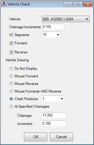
User inputs |
| Vehicle |
Select a
Vehicle Clearance Template from the pulldown menu. |
| Chainage
Increments |
Sets the
sampling frequency for checking clearance along the vertical
grading |
| VC Segments |
Sets how the vertical curves
are managed - select a number of chords to describe the
vertical curve. Recommended value: 10. |
| Forward |
Checks vehicle clearance in
forward direction. Calculates and displays
the lowest clearance line for the vehicle path on the
Vertical Grading window. |
| Reverse |
Checks vehicle
clearance in reverse direction. Calculates
and displays the lowest clearance line for the vehicle
path on the Vertical Grading window. |
| Vehicle Drawing |
These options set what will
be drawn on the screen of the Vertical Grading Editor. |
| Draw
Nothing |
Show
no vehicles. |
| Mouse
Forward |
Places
forward vehicle template in relation to mouse position
on screen |
| Mouse
Reverse |
Places
reverse vehicle template in relation to mouse position
on screen |
| Mouse
Forward and Reverse |
Places
forward & reverse vehicle template in relation to
mouse position on screen |
| Draw
at Specified Chainages |
Set
the chainage to start drawing the vehicle and the increment
at which the next vehicle will be drawn |
| Clash
Positions |
Sets
the clash position to place a vehicle at. Setting this
to 2 will place vehicle at clash position 2 |
| OK |
Apply and
exit. |
| Cancel |
Exit the
form without changing any data. |
|
|
 Vehicle Forward
 Vehicle Reverse
 Use Mouse Use Mouse |
Toggles
display depending on Vehicle Drawing options selected. |
| |
Sight
Distance Panel |
|
|
 Set
Design Criteria Set
Design Criteria |
Opens the Speed
Table form to establish sight
distance criteria to check.
Special Note: Once speed based design criteria
have been applied, any non-compliant vertical curves will be drawn
in RED in the
graphical area
|
| |
Tools
Panel |
|
|
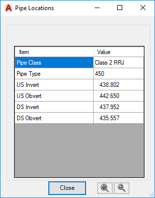
 Enquire Pipe Enquire Pipe |
Click on a pipe displayed
in the Graphical Display area to obtain details on the selected
pipe:
 |
|
Enquire
Elevation |
This command is used
to query the elevation at a particular chainage. Inputs are as
follows:
|
| Enter
Chainage |
Type
in the chainage to report the level |
| OK |
Exit the
form and display the level details at the defined chainage. Example
output as follows:
|
| Cancel |
Exit
the form without editing the IP's
|
|
| |
Design
Constraints Ribbon Tab |
 |
| |
|
Design Constraints
are a powerful design aid. They provide the ability
to show additional elevation information describing elevations
and projections from other features (eg: left edge of road, left
batter/daylight, a different string, another surface). Users
can snap design IP's onto these contraint profiles and visually
compare them to the current design string elevations.
Find more information about the full range of Design Constraints
via the Design
Data form help information. Summary information will be provided
below. |
| |
Manage
Panel |
|
|
Type |
Select the type of
Design Constraint from the picklist:
- Project Design (Alignment)
- User picks a design string and an alignment. Using
the horizontal positioning from the alignment, elevations
are adopted from the design string surface. Users
can then apply a slope to project elevations from the
reference point to the current string. Slope
projections are made perpendicular to the reference alignment.
Project Design (Code)
- User picks a design string and a code from the design
string. This sets the reference point elevations. Users
can then apply a slope to project elevations from the
reference point to the current string. Slope
projections are made perpendicular to the reference string/code.
- Project Surface (Alignment)
- User picks a surface and an alignment. This
sets the reference point elevations. Users
can then apply a slope to project elevations from the
reference point to the current string. Slope
projections are made perpendicular to the reference string/code.
- Show String
- User picks a string to display and an elevation adjustment. The
elevations from the string are projected directly onto
the current string.
- Show Surface (Alignment)
- User picks a surface and an alignment. This
sets the reference point elevations and these are projected
directly onto the current string.
- Show Surface (Code)
- User picks a surface, a design string and then a code. This
sets the reference point elevations and these are projected
directly onto the current string.
Inputs are provided relevant to the type of constraint being
applied |
|
List |
Lists the created design
constraints. Select one to make edits. Click
on the Apply button to apply the changes. |
|
 Create New Constraint Create New Constraint |
Allows creation
of a new constaint using the selected Type. Users are
prompted to name the constraint (required) |
|
 Delete current constraint Delete current constraint |
Deletes the current
Design Constraint shown in the List dropdown. |
|
Apply |
This is used to Create
and Update design constraints. |
|
 Update Update |
Forces a recalculation
and update of the design constraint linework. |
| |
Region
Panel |
|
|
Start
Chainage |
Start position for
the design constraint to display |
|
End Chainage |
End position for the
design constraint to display |
| |
Reference
Panel |
Users
establish the reference position (vertically and horizontally)
for the projection. Inputs here depend on the Type
selected. The horizontal position is firstly established
and then elevations are assigned at that position.
All possible options shown: |
|
Alignment |
Select the alignment
for horizontal position |
|
String |
Select the String for
design elevations |
|
Code |
Select the Code for
offset position (elevations adopted from the Code) |
|
Surface |
Surface for elevations |
| |
Details
Panel |
Move
the location of the reference point position (to simulate kerb
drop for example) and apply % grades (where relevant) |
|
Offset |
Offset the calculated
position horizontally. Positive moves to the right
of the centreline of the current string, and negative values to
the left |
|
Level
Adjustment |
Raise/Lower the calculated
position vertically. Positive is increases the elevation,
and negative decreases the elevation. |
|
Lower
Crossfall (%) |
Only shown for some
Types. Allows a % grade projection from the calculated
reference point location to the current string. |
|
Upper
Crossfall (%) |
Only shown for some
Types. Allows a % grade projection from the calculated
reference point location to the current string. |
| |
Display
Panel |
|
|
Lower
Colour/Colour |
Colour to draw the
'lower crossfall' projection.
For Types where projections are not included, this will show as
the Colour of the profile. |
|
Upper
Colour |
Colour to draw the
'upper crossfall' projection.
For Types where projections are not included, this will not display. |
|
Upper
Crossfall (%) |
Only shown for some
Types. Allows a % grade projection from the calculated
reference point location to the current string. |
|
Lower
Active/Active |
Tick on to display
lower crossfall. |
|
Upper
Active |
Tick on to display
the upper crossfall. |
|
Search
Offset |
Specify a search distance
for the constraint. Provides control for cases where
the alignment/code/string can be viewed twice at a cross section
and users want the closest one.
|
| |
Survey Ribbon Tab |
 |
| |
Settings
Panel |
|
|
Point
Groups |
Select a Point Group to
display. Points and Survey Linework will be displayed for this
point group, within the Search Distance specified |
|
Show Survey Points |
Tick to display Survey
Points in the graphical window. Point information is projected
onto the graphical window.
A marker and text will display for the points. Text will consist
of point property information such as the Point Description and Point
Elevation (in brackets).
Points located outside the Search Distance will not be displayed. |
|
Show Survey Points |
Tick to display Survey
Strings in the graphical window.
Survey Linework will be displayed as straight lines connecting
sequential survey points
Note: If Survey Points is unticked, this will display the point markers
and the survey strings. A Survey String segment will only display
if both Points connecting the start and end of the survey string are
located within the Search Distance. |
|
Search Distance |
Type in an offset distance
(measured from the String centreline) to display COGO Points.
All Points located outside this offset will not be displayed. |
|
Update Survey Data |
Updates the display of
points in the selected Point Group and usign the input Search Distance.
Useful if points have been added/edited/deleted with the Vertical
Grading Editor window open, or the Search Distance has been changed. |
|
|
Settings
Ribbon Tab |
 |
| |
Settings
Panel |
|
|
 Display Settings Display Settings |
The display of profile
grades, high/low points, level information and text size can be
controlled by the designer.
Note: These controls are mirrored in the
Active Drawing Settings - Vertical Grading tab.
The controls of the form are graphically outlined below:
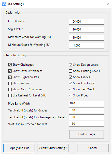
| Design Aids |
These settings assist the designer
in achieving design compliance |
| Crest
K Value |
Type
in the required K value for creating crest curves. At
the time of Adding
IP's in the Vertical Grading Editor
the software will use the specified K factor to indicate
a suitable vertical curve length to achieve the K factor
required for crest curves. |
| Sag
K Value |
Type
in the required K value for creating sag curves. At
the time of Adding
IP's in the Vertical Grading Editor
the software will use the specified K factor to indicate
a suitable vertical curve length to achieve the K factor
required for sag curves. |
| Maximum
Grade for Warning (%) |
Type
in a desirable maximum grade (%). If the incoming
or outgoing grade from a IP exceeds the maximum the grade
indicator will change colour. |
| Minimum
Grade for Warning (%) |
Type
in a desirable minimum grade (%). If the incoming
or outgoing grade from a IP is less than the minimum the
grade indicator will change colour. |
| Items to Display |
Set what textual and other graphical
information is displayed in the Vertical Grading Editor
Design Window. Some of the relationships
are shown, above |
| Show
Chainages |
Tick
on to show the Chainage values in the Vertical Grading
Editor window. This will show the alignment
chainages by default - if another road has been used for
chainages (Use
Other Road Chainages command), the other road chainages
will display here. |
| Show
Design Levels |
Tick
on to show the Design Levels (Elevations) of the long
section in the Vertical Grading Editor window |
| Show
Level Differences |
Tick
on to show the Level Difference between the Design Level
of the vertical grading and the Sampled Surface in the
Vertical Grading Editor window |
| Show
Existing Levels |
Tick
on to show the Existing (Sampled) Surface Levels in the
Vertical Grading Editor window |
| Show
High/Low Pt's |
Tick
on to highlight the location of the high/low points in
the Vertical Grading Editor window (small circle
located along the design grading) |
| Show
Grades |
Tick
on to textually display the grades either side of the
IP's and the Vertical Curve Lengths in the Vertical
Grading Editor window |
| Show
Volumes |
No
longer operational. Previously controlled whether
volume summary displayed when using the up/down by increment
command in the old command interface. |
| Show
Envelopes |
No
longer operational. Previously controlled whether
design constraints displayed after adding them in the
Design Data Form. |
| Show
Align. Chainages |
Tick
on to display the chainages of the current alignment (this
feature is only enabled subject to settings established
via the Use
Other Road Chainages command).
It is often useful to evaluate the levels of the current
String in relation to another Road alignment. |
| Show
Text XSect |
Not
used. |
| Use
Resheet For Level Diff. |
Tick
on to display the difference between the Design Levels
and applied Resheet Levels.
Note: This feature is only applied after a Resheet
has been applied to the Road - see below
for more information on applying a resheet to the
design. |
| Show
Pipes |
Tick
on to display Pipes designed using Civil Site Design on
the Vertical Grading Editor window. Perpendicular
pipes will be shown as a crossing pipe - all other pipes
are shown superimposed in full. |
| Pipe
Band Width |
Type
in a value to set the search offset (relative to the current
String being graded) to locate and display Pipes |
| Text
Height (pixels) for Grades |
Change the
pixel size for grade text shown at the top of the Vertical
Grading Editor (if displayed). Minimum
is 8 pixels. |
| Text
Height (pixels) for Chainages and Levels |
Change the
pixel size for grade text shown along the bottom of the
Vertical Grading Editor (vertical text, if displayed). Minimum
is 8 pixels. |
| %
of Display Reserved for Text |
This is
the percentage of space 'reserved' for text display at
the bottom of the form - the vertical grading minimum
level will extend down to this display percentage. |
|
Grid Settings |
Opens the Grid Settings form to control the defualts for grid
and crosshair display:
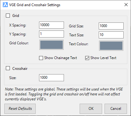
|
Grid |
Tick on to have the Grid display by default when the Vertical Grading Editor
Window opens |
|
X Spacing |
Type in an x offset for vertical grid lines |
|
Y Spacing |
Type in a y offset for horizontal grid lines |
|
Grid Colour |
Pick the colour of grid lines |
|
Grid Size |
Type in the total grid size (this is oriented about the CL point). Be sure
set a reasonable value to cover the cross section window |
|
Text Size |
Type in a text size |
|
Text Colour |
Pick a colour for the text |
|
Show Chainage Text |
Display text for the chainage (vertical) grid lines |
|
Show Level Text |
Display text for the elevation (horizontal) grid lines |
|
Crosshair |
Tick on to have the crosshairs display by default when the Vertical Grading
Editor Window opens |
|
Size |
Size of the crosshair in pixels |
|
Reset Defaults |
Reset to default values |
|
OK |
Save and exit |
|
Cancel |
Exit without applying |
|
| Apply
and Exit |
Apply
and exit. |
| Cancel |
Exit the
form without adjusting the display. |
|
|
 VGE Customise Display VGE Customise Display |
This command allows
the designer to customise the display of the Vertical Grading
Editor (VGE). Here, the designer can edit the size of text displayed
and assign colours to text and other items, such as the VGE background
colour.
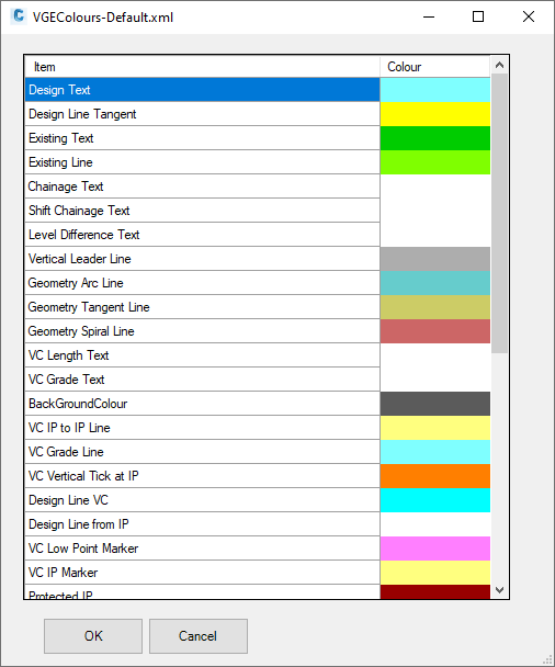
The Set
Vertical Grading Editor Window Colours command has further
information on this form. |
|
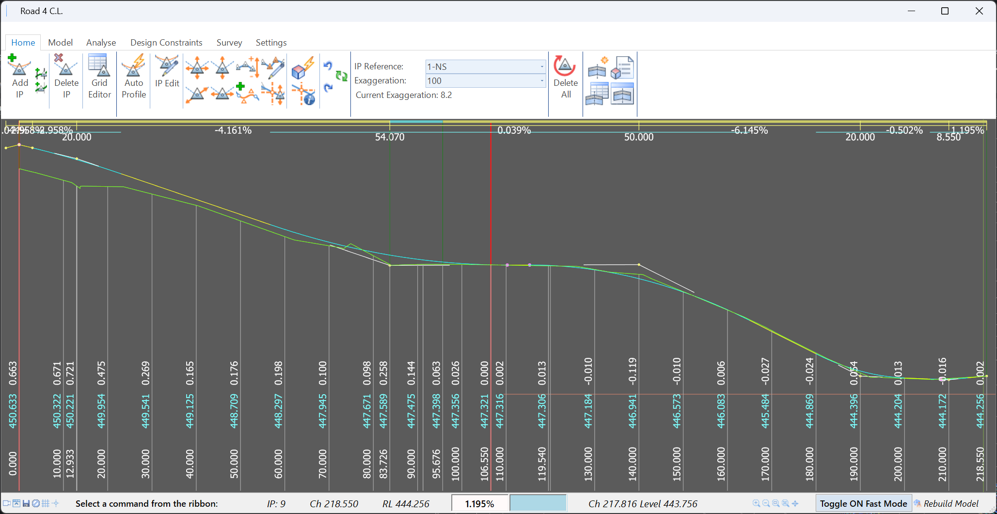
|
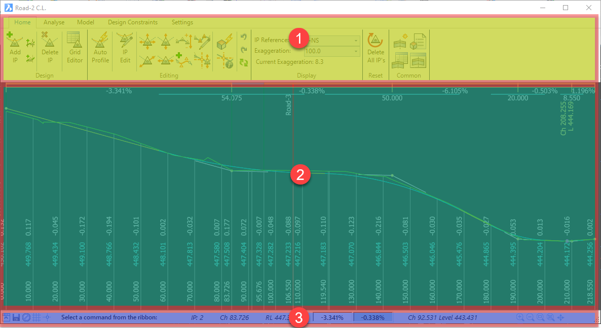
Information
Display Area (bottom) |
| |
|
 |
|
Video Link |
Click to display Youtube
videos related to the Vertical Grading Editor |
|
 Minimise View
 |
Click to minimise the Ribbon
to display only icons for the Home tab. Click again to restore
full ribbon display |
|
 Save
Save |
Save the design |
|
 Command Prompt
 |
Describes the command
details and gives instruction on executing a command in the VGE. |
|
 Grid on/off
 |
Turn on/off the display of a
Grid on the graphical display window |
|
 Crosshairs on/off
 |
Change the mouse position
from a picker icon to crosshairs |
|
Command Prompt |
Describes the command
details and gives instruction on executing a command in the VGE. |
|
Command Prompt |
Describes the command
details and gives instruction on executing a command in the VGE. |
|
IP,
Ch and RL |
Displays the IP number
(1 on left incrementing to the right), chainage and RL of IP closest
to mouse position |
|
Incoming Grade |
Displays the incoming
grade to the IP. Box will highlight blue if outside
desirable limits as described in the Settings. |
|
Outgoing Grade |
Displays the outgoing
grade from the IP. Box will highlight blue if outside
desirable limits as described in the Settings. |
|
Ch, Level |
Displays the chainage
and level of the mouse position in the VGE window. |
|
 Zoom In
 |
Zooms in by 25% |
|
 Zoom Out
 |
Zooms out by 25% |
|
 Zoom Window Zoom Window |
Pick a left and right
extents to zoom to those extents |
|
 Zoom Extents Zoom Extents |
Zooms to the start/end
extents of the String |
|
 Pan
Pan |
Pick a point to pan from a
point to pan to. |
|
Toggle On/Off Fast
Mode |
Enable/disable the Auto Update toggle in the Vertical Grading Editor.
When 'Fast Mode' is toggled on, editing in the Vertical Grading Editor
will not automatically update all models |
|
Rebuild Model |
Uupdate all Models (and
Surfaces) affected by edits made in the Vertical Grading Editor window |
 Create/Edit Templates form to facilitate creation/editing of cross
section templates
Create/Edit Templates form to facilitate creation/editing of cross
section templates