Model Builder
Icon: 

Introduction
By default, the  Auto Model command automatically collects together all the roads, kerb returns and cul-de-sacs and creates a totally integrated surface model of these features, including all trimming and creation of breaklines in the intersection zone.
This command allows the user to construct a model using any collection of CSD Objects/Strings (roads, kerb returns, cul-de-sacs, knuckles, strings, etc) and cross section Codes created in the drawing. Users include CSD Objects (inclusive of their cross section Codes) and have a range of editing tools for trimming out Codes that are not required in the model. Common uses for this application includes the design of roundabouts as part of an intersection reconstruction, inclusion of traffic islands, angled parking and more.
Model Builder allows the designer to construct a model using any collection of Strings and Codes - pick the String object and select the code linework to display. Users control the chainage range for display of linework data.
The model construction happens directly in the drawing - the designer can control the colour of the linework (based on the Code) as well as the transparency of background linework.
Zoom and pan can happen directly in the drawing. The modelling system is accessed from a floating form on the drawing canvas.
A subgrade model can also be built from a model, see
Subgrade Model
Manager.
Setting Display Defaults
The default display controls are set in the  Active Drawing Settings>Modelling Tab form. In here the designer sets:
- A transparency to apply to all background linework (any AutoCAD drafting or other CSD model linework/surfaces not related to the current model being edited). BricsCAD users: If Transparency is set to 100%, then all non-model linework will turn OFF.
- A Model Colour File (which controls linework colours) to apply to the linework of the active model you are editing
- A Model Colour File (which controls linework colours) to apply to the linework of all other models already created
These Model Colour Files are created from inside the Model Builder form.
Important note about Transparency - the Transparency setting will only be applied if Transparency has been enabled in the drawing - this is a small icon/text button at the bottom of the CAD environment in the same group of buttons as the Snaps.
Plotting Outputs
As well as being able to plot the surface information on long and cross sections, designers are able to extract the Model strings for display on cross sections. This has the added benefit of allowing the designer to control which Codes from the Strings to plot in the data rows/bands. Users can selectively choose what grade break information is important and required in the data rows, rather than trying to filter all grade breaks.
At the time of plotting cross sections, the Model can be included by applying the Add Model/Surface option in the Cross Section Data Bands/Controls form. Review the cross section plotting for more information on this form and the inputs.
Notes for Selecting and Editing CSD Objects
- Initially when the Edit button is selected, the designer will need to pick a String in the drawing to edit
- Thereafter the designer clicks a button in the Edit panel to change the String to edit.
Details
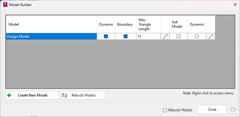
Upon starting the command the following form is displayed:
|
|
|
Displays a list of all created models. Note:
Right click for menu options, see below details.
|
|
Model |
Displays the model name. Double clicking on the model name will open it
for editing.
|
|
Dynamic |
Denotes whether the model is rebuilt when i) the Rebuild Model button is
run, ii) the Rebuild Models option is Ticked and the Model Builder form is closed, iii)
the
 Rebuild All command is run.
Note: Does NOT effect Compute Design Models thread, all
models are rebuilt when this thread is run.
|
|
Boundary |
Denotes whether the boundary retraction is applied to the model surface.
Boundary retraction delete triangles, working from the outside in (retraction) applying the
maximum triangle length. Once a triangle is found with a smaller value than
the maximum triangle length, triangle deletion stops.
|
|
Max. Triangle Length |
Set a maximum triangle length. This is used for boundary retraction.
|
 |
Open the right click menu options, see below for details.
|
|
Sub Model |
Denotes whether a subgrade model has been created from the model.
Note: This is for information only and cannot be ticked
on or off.
|
|
Dynamic |
Denotes whether the Subgrade Model is dynamically updated.
|
|
|
Open the Subgrade
Model Manager command.
|
|
[Right Click Menu] |
Select a Model and right click for menu options |
|
|
|
Edit Model |
Open the selected saved model for editing
|
|
Create/Edit Sub Model |
Open the
Subgrade Model Manager command.
|
|
Rebuild Model |
Rebuild the selected model.
Note: Dynamic must be toggled ON.
|
|
Rebuild Models |
Rebuild all models.
Note: Only models with dynamic
toggled ON will be rebuilt.
|
|
Surface Manager |
Open the
Surface Manager command. |
|
Toggle Display |
Opens the
Toggle Display command. |
|
Copy Model |
Creates a copy of the current model and opens the copy for
editing. |
|
Delete Model |
Deletes the current model. |
|
|
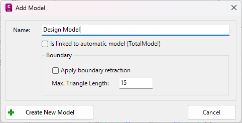
Create New Model |
Create a new model. Upon running the command the following form is
displayed: |
|
|
|
|
|
Name |
Enter the name for the model.
|
|
Is linked to automatic model (TotalModel) |
Create a model linked to the same model that is created
from the
Auto Model command, which includes automated intersection(s), cul-de-sac(s), knuckle(s) and other trimming.
Note: The software adds code
trimming to match Auto Model. Whilst these code trims cannot be edited,
users can overwrite them by adding further code edits.
|
|
Boundary |
Setup the boundary options for the model. |
|
Apply boundary retraction
|
Denotes whether the boundary retraction is applied to the
model surface.
Boundary retraction delete triangles, working from the outside in (retraction) applying the
maximum triangle length. Once a triangle is found with a smaller value than
the maximum triangle length, triangle deletion stops.
|
|
Max. Triangle Length
|
Set a maximum triangle length. This is used for boundary
retraction.
|
|
Create New Model
|
Creates the model and opens it for editing.
|
|
Cancel |
Exit the form. |
|
|
Rebuild Models |
Rebuild all models.
Note: Only models with dynamic toggled ON will be
rebuilt.
|
|
Close |
Exit the form.
|
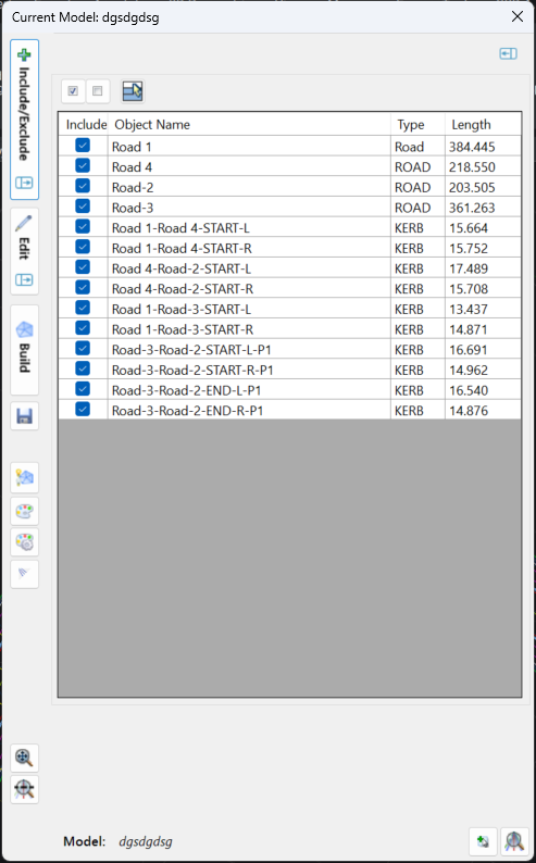
Once a model is selected the following form is displayed as a floating toolbar, allowing for editing of the model:
 |
|
Include/Exclude Flyout
|
Click on the Include/Exclude button to expand and display the Include/Exclude Editor within the display window
 |
|
 Minimise Minimise
|
Minimise the Model Manager form back to a strip bar.
|
|
Group Selection Tools
|
The command icons above the spreadsheet provide quick access controls for CSD Objects in the list.
|
|

|
Includes the highlighted CSD Objects in model. If no CSD Objects are highlighted then all CSD Objects are ticked on for inclusion.
Note: In the list of roads, use the [Shift] and [Ctrl] buttons while selecting rows to select multiple items
|
|

|
Excludes the highlighted CSD Objects in model. If no CSD Objects are highlighted then all CSD Objects are ticked off for exclusion.
Note: In the list of roads, use the [Shift] and [Ctrl] buttons while selecting rows to select multiple items
|
|

|
Deselects all rows. If any row/s are highlighted, this command button removes the highlights.
|
|
CSD Object Listing
|
Every CSD Object is listed here. Items that are ticked on are included in the model. Items that are ticked off are excluded.
|
|
Included
|
Denotes whether the CSD Object is included or excluded from the model. Click on each row to tick on/off the CSD Object.
|
|
Object Name
|
Lists the name of the CSD Object (normally matching the alignment name). This cell is non-editable, however users can select multiple rows by clicking in this column.
|
|
Type
|
Details the CSD Object Type. Types include Road, Kerb, Cul-de-sac, Knuckle, String. This cell is non-editable.
|
|
Length
|
Details the object length - this typically matches the alignment length. This cell is non-editable.
|
|
| Edit Flyout |
Click on the Edit button to expand and display the Edit form within the display window.
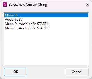
If no CSD String is selected, the user will be prompted to select a string to edit as follows:
Special Note: The Edit form lists the edits applied to the Current CSD Object.
 |
|
Minimise
|
Minimise the Model Manager form back to a strip bar.
|
|
Current Road
|
Lists the current Road (String) being edited.
|
|
 Pick String From List Pick String From List
|
Pick a String to edit from a list of all String objects created. Select a string to edit and click OK to make it current for editing
|
|
 Pick String from Drawing Pick String from Drawing
|
Pick a new String to edit from the drawing
|
|
 Edit/Trim By Selection Edit/Trim By Selection
|
Select this option to exclude (delete) selected Codes over a chainage range.
At the command prompt at the bottom, graphically select the start chainage and end chainage over which to apply the edit.
The editing form is partly modeless, enabling zoom and pan in the display window, as well as updating of the model display as edits are applied. Inputs are as follows:
|
|
|
Chainage Range to Apply
|
Sets the chainage range over which the selected edit will apply.
|
|
Start
|
Set the start chainage using the pick list of chainages - these are the sections sampled for the String.
|
|
Pick Start from Drawing
|
Pick the start from the drawing.
|
|
 (Add Extra Sampling)
|
Opens the  Add Extra Sections form allowing for extra sampling to be added to the current string and assigned to the Start Chainage. Add Extra Sections form allowing for extra sampling to be added to the current string and assigned to the Start Chainage.
|
|
To End
|
Set the start chainage using the pick list of chainages - these are the sections sampled for the String.
|
|
Pick End from Drawing
|
Pick the end from the drawing.
|
|
(Add Extra Sampling)
|
Opens the
Add Extra Sections form allowing for extra sampling to be added to the current string and assigned to the End Chainage.
|
|
Add Region
|
At the command prompts, select the first Chainage and second Chainage over
which to apply the edit. The software will automatically determine the
start and end chainage from the locations selected, and will automatically
insert sampled sections at the locations selected to force the edit to apply at
the exact locations selected.
|
|
|
Deselects all rows. If any row/s are highlighted, this command button removes the highlights.
|
|
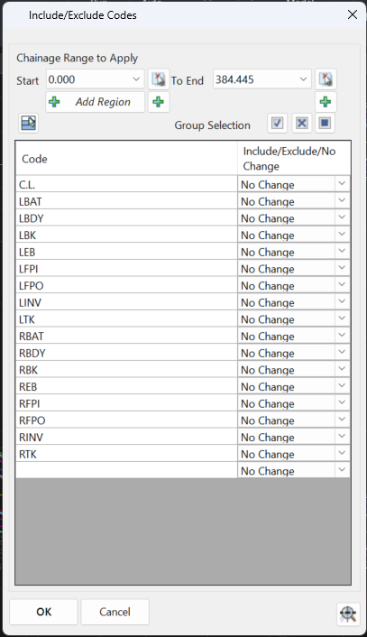
Group Selection
|
These command icons above the Code List provide quick include/exclude Code control for selected Codes in the Code List.
|
|
|
Includes the highlighted Codes from the model. If no Codes are highlighted then all Codes are set to an 'Include' status. This option is good to force inclusion of Codes that have been excluded from the model.
Note: In the list of Codes, use the [Shift] and [Ctrl] buttons while selecting rows to select multiple items.
|
|

|
Excludes the highlighted Codes from the model. If no Codes are highlighted then all Codes are set to an 'Exclude' status.
Note: In the list of roads, use the [Shift] and [Ctrl] buttons while selecting rows to select multiple items.
|
|

|
Leaves the current include/exclude status of the Code alone (No Change) for highlighted Codes. If no Codes are highlighted then all Codes are set to a 'No Change' status.
Note: In the list of roads, use the [Shift] and [Ctrl] buttons while selecting rows to select multiple items.
|
|
Code List
|
Every code for the selected Road Object are included here. Users are able to set whether the Code is included, excluded, or unchanged over the selected chainage range. Columns are as follows:
|
|
Code
|
List of Codes for the object being edited.
|
|
Include/Exclude/No Change
|
Set the status of the Code to be excluded from the model (Exclude), included in the model (Include) or status unchanged (No Change).
|
|
OK
|
Apply the edit and exit. The edit can be adjusted in the Edit Flyout (see below)
|
|
Cancel
|
Do not apply the edit and exit the form
|
|

|
Zooms to the selected chainage range.
|
|
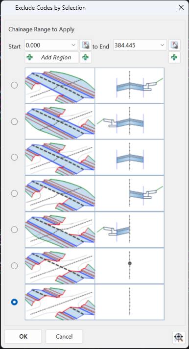
 Edit/Trim by Group Edit/Trim by Group |
Select this option to delete groups of codes over a chainage range.
At the command prompt at the bottom, graphically select the start chainage and end chainage over which to apply the edit.
The editing form is partly modeless, enabling zoom and pan in the display window, as well as updating of the model display as edits are applied. Inputs are as follows:
 |
|
Chainage Range to Apply
|
Sets the chainage range over which the selected edit will apply.
|
|
Start
|
Set the start chainage - initially populated from graphical selection in the drawing.
|
|
Pick Start from Drawing
|
Pick the start from the drawing.
|
|
(Add Extra Sampling)
|
Opens the
Add Extra Sections form allowing for extra sampling to be added to the current string and assigned to the Start Chainage.
|
|
To End
|
Set the end chainage - initially populated from graphical selection in the drawing.
|
|
Pick End from Drawing
|
Pick the end from the drawing.
|
|
(Add Extra Sampling)
|
Opens the
Add Extra Sections form allowing for extra sampling to be added to the current string and assigned to the End Chainage.
|
|
Add Region
|
At the command prompts, select the first Chainage and second Chainage over
which to apply the edit. The software will automatically determine the
start and end chainage from the locations selected, and will automatically
insert sampled sections at the locations selected to force the edit to apply at
the exact locations selected.
|
|
Group Exclusion List
|
Graphical representation included to show the grouping of Codes to be removed. This group of edits enable quick construction of intersections and other connecting road features.
|
|
Radio button selection
|
Use the radio buttons to select the desired edit.
|
|
OK
|
Apply the edit and exit. The edit can be adjusted in the Edit Flyout list.
|
|
Cancel
|
Do not apply the edit and exit the form.
|
|
|
Zooms to the selected chainage range.
|
|
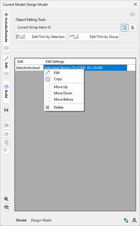
| Edits List |
Lists all the edits applied to the String. Click on the edit to highlight it in the drawing - edits are highlighted with lines located at the start and end of the edit. |
| Edit |
Lists the edit type. Click here to highlight the edit extents in the drawing. |
| Edit Settings |
Describes the edit details. Select and right click to enable the following options:
- Edit: Opens the edit form for the applied edit, to enable changing the edit method, codes and/or chainage range
- Copy: Copy the selected edit
- Move Up: move the highlighted edit up in the list
- Move Down: move the highlighted edit down in the list
- Move Before: move the highlighted to a selected location in the list
- Delete: Delete the selected edit
|
|
 Build Build |
Creates an CSD Surface of the model - the name of the model will be BM-<Model Name>. |
|
 Save Save
|
Save changes to the current model. |
 Toggle Display Toggle Display |
Opens the
 Toggle Display form allowing display and rebuild control for all the linework and surfaces for each CSD Model. Toggle Display form allowing display and rebuild control for all the linework and surfaces for each CSD Model. |
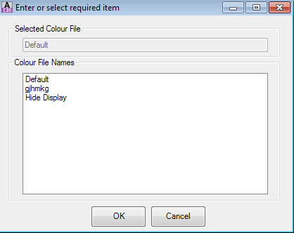
 Select Colour File Select Colour File |
Click to select a Model Colour File to apply to the current Model, then the other Models not being edited. This file describes the colour to apply to the linework based on the Codes.
 |
|
Select Colour File
|
Displays the current Colour file applied to the Model (either the current Model or the other Models, as noted in the title).
|
|
Colour File Names
|
List of Model Colour Files that can be applied to the Model for linework display.
|
|
OK
|
Apply.
|
|
Cancel
|
Exit without applying.
|
|
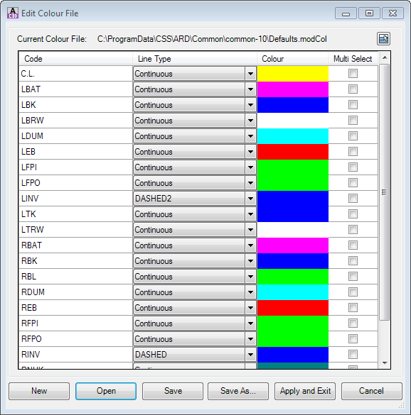
 Edit Model Colour File Edit Model Colour File |
Users can specify the colours used in the display. Form controls are as follows:
 |
|
|
Deselects all items ticked in the Multi Select columns.
|
|
Code Colour Table
|
List of codes with user control over the code display. Controls are:
|
|
Code
|
The list of codes is populated from the total list of Codes included in all the CSD Objects in the project
|
|
Line Type
|
Not currently implemented. This is intended to control the presentation of linework in the AutoCAD drawing.
|
|
Colour
|
Set the Colour for display and output. This is achieved by clicking on a colour swatch for one of the Codes.
The AutoCAD Color Palette will display for users to select a colour. Setting colour to Bylayer will not be accepted.
Note: All Codes that have Multi Select ticked ON will all be adjusted based on the colour change made to the selected Code
|
|
Multi Select
|
Any Codes ticked in Multi Select will have their colour set when the colour is adjusted for any Code.
|
|
New
|
Create a new colour mapping file to use
|
|
Open
|
Open an existing colour mapping file
|
|
Save As...
|
Save a copy of the current colour mapping setup
|
|
Save
|
Save the current colour mapping setup
|
|
Apply and Exit
|
Save the current colour mapping setup and exit the form. These colours will be immediately applied in the display window
|
|
Cancel
|
Cancel the changes and return to the model
|
|
 / /
 Show/Hide Excluded Codes Show/Hide Excluded Codes |
Toggle button to display/hide excluded Codes. Default setting is to hide excluded Codes - when show option selected the removed Code linework show as greyed out lines. |
|
 Zoom All Zoom All
|
Zoom drawing to current model extents. |
|
Zoom to a Chainage
|
Zoom to a selected string and chainage. |
|
Model: |
Displays the name of the current model |
 Add Extra Sampling
 |
Opens the
Add Extra Sections
form allowing for extra sampling to be added to the current string.
|
 Zoom to Current Road Zoom to Current Road |
Zoom to the current road/string. |
Click on the X at the top right of the form to close the model. The
Toggle Display form will open for the user to select what models and linework to display upon exit.