Toggle Display
| Icon: |
Introduction
Often it is desired to quickly turn surface display on/off for major elements such as the mesh and contours, as well as to change the contour intervals. This form provides a quick method for managing the basics of surface display - this is particularly useful when there are multiple surfaces in the project.
It also provides similar controls over Models and Section lines.
Changes made are written to the Outputs control for each surface.
This is not a modeless form, it must be closed before work can continue in the drawing.
Details
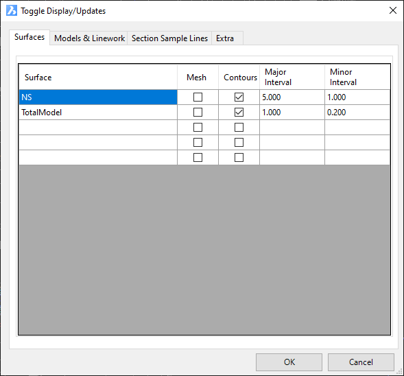
Upon selecting the command the following form is displayed:
 |
|||||||||||||||||||
| Surfaces Tab | Lists the objects and the main toggle control options, as shown above. | ||||||||||||||||||
| Surface Name | Lists each Surface in the drawing. Click on the toggles or in the cells to make changes. | ||||||||||||||||||
| Mesh | Tick to turn On/Off the display of the mesh or triangles. | ||||||||||||||||||
| Contours | Tick to turn On/Off the display on the contours. This control effects all types of contours. | ||||||||||||||||||
| Major Interval | Type in the value of the Major Contour interval required. | ||||||||||||||||||
| Minor Interval | Type in the value of the Minor Contour interval required. | ||||||||||||||||||
| OK | Apply and exit. | ||||||||||||||||||
| Cancel | Exit the form without making changes or use the Windows Red-X. | ||||||||||||||||||
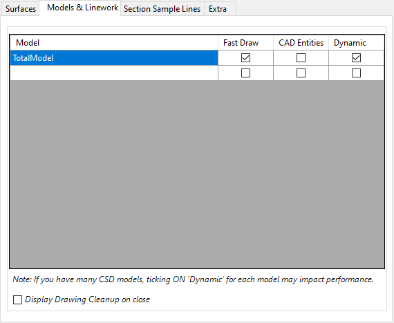
| Model & Linework Tab | Lists the objects and the main toggle control options. Tab shown below. Models and Linework equate to breaklines of features, for example, kerb lines (top, back, lip), footpaths and centrelines, etc. |
||||||||||||||||||
|
|||||||||||||||||||
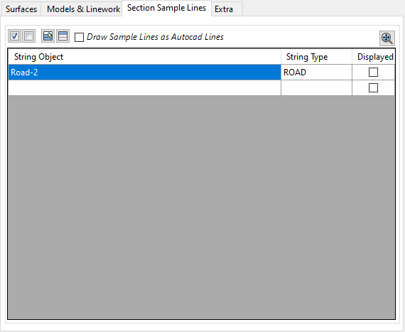
| Section Sample Lines Tab | Lists the String objects and the main toggle control options. Tab shown below. Sample Lines are the lines that represent the overall width of sampling taken perpendicular to the corresponding alignment string object, typically for cross section plotting purposes. |
||||||||||||||||||
|
|||||||||||||||||||
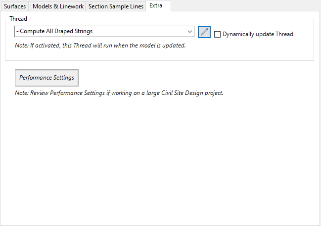
| Extra Tab | Provides additional controls | ||||||||||||||||||
|
|||||||||||||||||||
 All ON
 All OFF
 Deselect All
 Invert Selection