Combined Surface
Icon: |
|
| Ribbon: | Roads Tab > Select Panel > Model Viewer Dropdown > Combine Surfaces |
| Model Viewer: | Outputs Tab > Combined Surfaces |
Introduction
The Combined Surface command will output a Civil Site Design Surface (with prefix COMB-), which has been created by pasting multiple surfaces into a defined Base Surface.
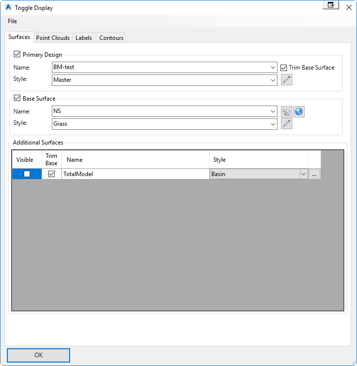
This command is often used in conjunction with Model Viewer, because the same routines are used for the display of multiple surfaces in 3d. In Model Viewer, the surfaces displayed in the 3d visualisation can be set to trim the defined Base Surface to avoid overlapping surfaces. Prior to outputting a Combined Surface, it is recommended to review this surface in Model Viewer. The Model Viewer Toggle Display form is used to specify the surfaces that will be combined.
Updating of the created Combined Surface can be done in multiple ways.
1. By running Build Surface in the Civil Site Design Surface Manager. The Surface Manager can be used to apply boundaries and edits to the combined surface.
2. By running the Combined Surface command again, but selecting Update Surface when prompted.
3. By running the Combined Surface Settings command. This command allows the user to update multiple combined surfaces and specify the order in which the update occurs.
4. By creating a Thread and adding the Compute Combined Surface action.
Details
Upon selecting the command the following form will display. This form is used to specify the surfaces to combine. More information on the Toggle Display form can be found here.
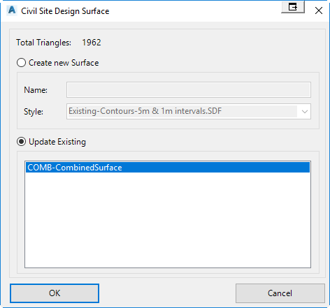
After selecting OK, the Civil Site Design Create Surface dialog will display. The user has the option to create a new combined surface or updating an existing combined surface.