Design Rules and Terms Used
Introduction
In order to get the best out of this software, users must understand how the software works as well as the design conventions which must and/or should be adopted in the design process.
Here are some notes on the best design processes.
Details
Software Data Files
CSD stores data in an external folder for processing, and as a backup if the drawing stops unexpectedly. More information on this can be found in the CSD General help system.
By default, when a project is started a folder is created at the same location as the current drawing (with a name matching the current drawing name and with -Data added as a suffix). Project data is stored in this folder.
The folder location can be manually set by the user - see the CSD General help system for more information on how to do this..
Surfaces
Extents
The software works by reading an 'Existing' surface and using these levels to generate an 'EXISTING' surface profile for the Road objects created with the software.
The Existing surface is initially assigned in the Design Settings tab of the ![]() Active Drawing Settings form, however it can be edited for any Road object created.
Active Drawing Settings form, however it can be edited for any Road object created.
For this to be successful the following criteria MUST be adhered to::
- The surface created MUST extend for the full length of EVERY alignment - if the software cannot find 'existing' surface levels at every single station along the alignment you may receive error messages and problems in processing the data using the software.
For Civil 3D customers, a Civil 3D surface is normally set as the 'existing' (or survey) surface from which the design levels are calculated against.
For non-Civil 3D customers, a Surface must be created in Civil Site Design using the Create/Edit Surface command.
Auto Surface Model - Information
By default, CSD creates a surface called TotalModel when the ![]() Auto Surface Model command is run. Some things to know:
Auto Surface Model command is run. Some things to know:
- The surface model Build setting has been adjusted to allow crossing breaklines and to use the average level at the point of crossing. This has been done to allow for widening the feature line of the kerb (when the stations don't match up there is always a small overlap) and because the levels will be so close as to not affect the model. This speeds up the terrain modeling an suppresses many superfluous 'error' messages upon building the surface
- The extents (batter to batter) is automatically determined and typically accounts for any overlaps (bow ties). If exporting the surface from CSD to make a Civil 3D Surface, the boundary will need to be redefined inside Civil 3D to remove loops.
- At the ends of roads, where cul-de-sacs are not provided, the software will tend to put in spurious triangles across to other Roads. It is recommended to set a Maximum Triangle Length to manage this
- Exporting to Civil 3D repeatedly will not delete the existing Civil 3D surface - it will just replace the breakline file used to build the surface.
Alignments
Alignments are integral to the software. The software works by reading alignments in the drawing to obtain horizontal geometry controls for all features including:
| Alignment Type (Set this Type in the CSD Alignments) |
Alignment Description Prefix (required in Civil 3D) |
How CSD Uses the Alignment |
| String (general purpose object)) | <None Required> | EVERY object is a String. A String is an object that contains horizontal and vertical geometry, with or without attached cross section elements.
A String can be plotted, set out or used in the construction of a surface. |
| Road | r- | Roads are special Strings that automatically match levels at intersections and can also be used to connect to Kerb Returns, Cul-de-sacs and Knuckles (elbows). The profile (vertical grading) can be reviewed and designed using the Vertical Grading Editor.
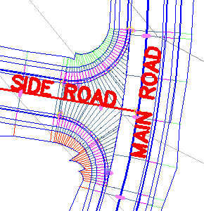
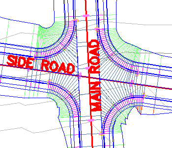
For intersections to form, Road centreline alignments must either STOP or START at the centreline of another road alignment or cross over another road alignment. Side Roads 'read' the cross sections of Main Roads at the intersecting point. There is a 'connection point code' expected on the Main Road to enable connection of the Side Road to the Main Road cross section. |
| Ker Return | k- | Kerb returns are special Strings that read and connect to the horizontal and vertical geometry from the nominated edge of Road code (the 'connection point code') of a Main and Side Road at an intersection. They are automatically incorporated into an Automatic Road Model.
Note: the software can automate the kerb return creation process INCLUDING creation and editing of the alignment, using one of the following commands:
For most cases, using the automated processes will be far easier and more efficient than creating and/or editing the alignment manually. |
| Cul-de-sac | cds- | Cul-de-sacs are special Strings that read and connect to the horizontal and vertical geometry of a Road, by matching to a selected Code on the connecting Road. They are automatically incorporated into an Automatic Road Model.
Note: the software can automate the cul-de-sac creation process INCLUDING creation and editing of the alignment
For most cases, using the automated processes will be far easier and more efficient than creating and/or editing the alignment manually. |
| Knuckle | n- | Knuckles are special Strings that connect to a selected Code on a Road. They automatically match to the Road Code, and automatically trim out the Road overlapping codes at the time of constructing an Automatic Road Model.
Note: the software can automate the knuckle creation process INCLUDING creation and editing of the alignment
For most cases, using the automated processes will be far easier and more efficient than creating and/or editing the alignment manually. |
| Roundabout | <None Required> | These alignments must exist already before starting the Roundabout command. An inner (island) and outer circulating carriageway alignment is expected for the Roundabout command. |
| Off Ramp | l- | Can be used to form a linking road between other CSD design objects (normally Roads). This type of object can be useful in the construction of off ramps and other 'joining' objects |
Alignment Geometry
- Geometrically, the alignment needs to be connected. Civil 3D allows you to have unconnected alignments, however this will not be accepted by the Civil Site Design software.
- Intersections
- The Centreline of Side Road alignments should ALWAYS be SNAPPED onto the Centreline of any Main Road alignment - otherwise the software may not interpret them as 'connecting'
- Road Centrelines should no have kinks in the alignment - direction changes should be supported with horizontal curves. If there are direction changes without horizontal curves, kerb return geometry can fail.
- Crossing Alignments are acceptable in the software
- For Every Intersection, there must be sufficient alignment length in every direction from the intersection point. The general rule is to have alignment lengths extending beyond the intersection point of length AT LEAST two times the radius of the kerb returns to be created at the intersection. This is required for the level sampling required to generate the kerb return profiles and for the software to iterate along the Main and Side Road corridors to locate a kerb return alignment connecting to both road edges and tangential to the corridor centrelines
- Alignments, in general, should be at least 30 metres (100 feet) long to satisfy most intersection requirements (this can go much lower depending on the cross section sampling frequency and the radius of any kerb return alignments.
- Loop Roads
- Alignments that loop back on themselves (such as a 'P' shaped alignment) are currently not supported by the Kerb Return routines.
- Looped road alignments can be broken into two alignments at a convenient point so that there is not a loop. In order to ensure continuity, the Designer will need to ensure the vertical grading matches at the beak point, otherwise the rest of the processing works as normal.
Other Considerations
- Do not create alignment for Roads that lie on top of one another - this will create additional intersections and kerb returns which will cause the software to build invalid models.
- It is recommended that Designer give their alignments the name that they want to have for the Roads - the software will set the Road names to match alignment names. There is a command enabling renaming of Road alignments.
- Each alignment must be FULLY contained within the 'Existing' surface for the entire length of the alignment
- In Civil 3D, Station Equations are NOT supported by Civil Site Design - expect unusual results or errors if station equations are used. It is however acceptable to use a different Starting Station for the alignment (instead of the starting station being zero)
- In Civil 3D, never use the Civil 3D Reverse Alignment command - Civil Site Design is not designed to cater for the alignment changes made after this routine has been run
Automated intersection detection and attachment of Cul-de-sacs and Knuckles
Civil Site Design has been set up to permit automatic processing of Intersections, Cul-de-sacs and Knuckles.
The automated processing is substantially quicker than trying to do things manually and it allows for a great deal of flexibility in the profile design. Any modification to a critical road in the vertical or horizontal sense can be carried through to all dependent road objects in a matter of seconds.
In order to make the automated processing work, the software makes use of the feature lines that define the edge of the road, coded as EB by the previous software. The Designer, however, has complete control over the feature line code (or label) used to define the edge of the road, since the designer creates ![]() Templates using Civil Site Design. These typical cross sections (or templates) are created within Civil Site Design and can be applied to any road in your project. These special assemblies can also be made 'public' and available to copy locally to any project - once the library of typical cross sections is developed it can be used multiple times.
Templates using Civil Site Design. These typical cross sections (or templates) are created within Civil Site Design and can be applied to any road in your project. These special assemblies can also be made 'public' and available to copy locally to any project - once the library of typical cross sections is developed it can be used multiple times.
The connection point label used for the road corridors to define the edge of the road is set in the Connection Point Codes tab of the ![]() Active Drawing Settings
Active Drawing Settings
Civil 3D Corridors and Civil Site Design
CSD is able to export out the automated road network model as a Civil 3D corridor. At the time of creation of the corridor, all profiles will be exported and a trimmed corridor model will be created to match the Auto Model command.
In order for this to work, it is imperative that the drawing contain a Civil 3D assembly named CORRIDOR-EZY and that it contain a specific subassembly applied once on the left and right sides of the assembly..
More information on this is available from the ![]() Auto Create Corridor command help.
Auto Create Corridor command help.
Subgrade Layers at Intersections - Kerb Returns, Roundabouts, Knuckles and Cul-de-sacs
In order for the kerb returns, cul-de-sac, knuckle and roundabout cross sections to be able to stretch out into the intersection areas AND include subgrade layers for the pavement, designers MUST include in the relevant templates (see ![]() Create/Edit Templates) a Code information to accommodate this. More information in the Templates command.
Create/Edit Templates) a Code information to accommodate this. More information in the Templates command.
A special Code is used by the software to match up to interesection geometry as follows:
- Kerb Returns
- Clockwise Direction: the kerb return cross section should include a Code called LDUM - this will connect to the edge of the main road and the centreline of the side road.
- Anti-Clockwise Direction: the kerb return cross section should include a Code called RDUM - this will connect to the edge of the main road and the centreline of the side road
- Cul-de-sacs
- Clockwise Direction: the cul-de-sc cross section should include a Code called RDUM - this will connect to the edge of the main road and the centreline of the side road.
- Anti-Clockwise Direction: the cul-de-sac cross section should include a Code called LDUM - this will connect to the edge of the main road and the centreline of the side road.
- Knuckles
- Either LNUK or RNUK depending which side you need the pavement to stretch