Automatic Ease Properties
Icon: ![]()
Menu: Roads > Edit > Automatic Ease Properties
Ribbon: Roads Tab > Edit Panel > Automatic Ease Properties
Introduction
Civil Site Design automatically adjusts Side Road profiles so that they cally assign a vertical curve 'ease' between the Side Road profile and extending to the edge of the main road (including matching the cross fall of the main road). This vertical curve ease is defined by a parabolic vertical curve length and a distance from the edge of the Main Road corridor for the IP.
This is set initially by the settings defined in the Road Details tab of the
![]() Active Drawing Settings form.
Once a Road string is created, this setting is assigned from the Active Drawing
Settings form to the individual Road string. Set the default behaviour for
all future projects by changing the settings in the
Active Drawing Settings form.
Once a Road string is created, this setting is assigned from the Active Drawing
Settings form to the individual Road string. Set the default behaviour for
all future projects by changing the settings in the
![]() Global Drawing
Settings form.
Global Drawing
Settings form.
This command facilitates the application of different vertical curves 'eases' for different intersections along each Side Road profile. For each 'ease' location (start/end or middle for intersecting roads, defined by a chainage range) the Designer can turn the ease on/off or change it's parameters.
The IP and Vertical curve assigned here is 'protected' during editing in the
![]() Vertical Grading Editor
since it is a design control which is set in this form.
Vertical Grading Editor
since it is a design control which is set in this form.
As well as being able to edit/set the automatic vertical curve 'ease' when
creating a Road String or using the
![]() Resample
Road Cross Sections form, use this command to change the vertical curve ease
settings for Road Strings.
Resample
Road Cross Sections form, use this command to change the vertical curve ease
settings for Road Strings.
Details
At every intersection the designer can choose to apply a vertical curve 'ease' to transition the profile from the side road grading up to the levels and grading of the Main Road cross section at the intersection.
Whilst this is initially set by the
![]() Active Drawing Settings form, designers can adjust the parameters using this command.
Active Drawing Settings form, designers can adjust the parameters using this command.
An example of an automatic ease is shown in the following Vertical Grading Editor window:
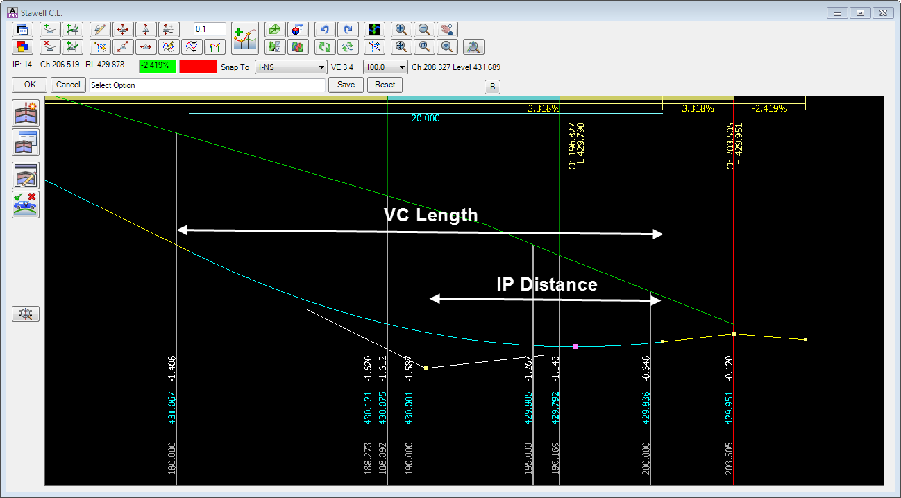
A 20 unit ease vertical curve length has been applied (VC
Length). |
Upon selecting the command the following form is displayed:
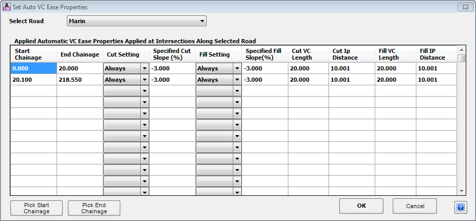 The intention is for designers to set Chainage ranges and vertical curve 'ease' conditions to apply within those ranges. Each line here represents a range, and within each chainage range vertical curve ease conditions have been set. Add extra lines to set different chainage ranges and different conditions. |
|
| Select Road | Use the pick list to select which Road to change the 'ease' for. |
| Use the Starting and Ending Chainage to set a range. Within this range designers can set VC lengths, IP distances and other ease conditions: | |
| Start Chainage | Set the starting chainage for a chainage range |
| End Chainage | Set the ending chainage for a chainage range |
| Within the starting and ending chainage range, set the vertical curve 'ease' conditions: | |
| Cut Setting |
Pick list to set the 'ease' conditions when the intersection point of the side road alignment and the main road edge is in CUT - options are:
|
| Specified Cut Slope (%) | If the Cut Setting is set to Fixed Slope, type in the fixed slope to locate the IP to apply for the vertical curve ease. |
| Fill Setting |
Pick list to set the 'ease' conditions when the intersection point of the side road alignment and the main road edge is in FILL - options are:
|
| Specified Fill Slope (%) |
If the Fill Setting is set to Fixed Slope, type in the fixed slope to locate the IP to apply for the vertical curve ease. The IP is measured from the edge of the Main Road (normally the ETW point code) represented on the Side Road profile.
Note: The IP will automatically be reset if required so that it is at least 1/2 of the Parabolic Curve Length. |
| If the Setting (cut or fill) is set to Always, Fixed Slope or Reverse then the following settings apply within the starting and ending chainage range: | |
| Cut VC Length |
Type in the vertical curve length to apply when the intersection point of the side road alignment and the main road edge is in CUT . The IP is measured from the edge of the Main Road (normally the ETW point code) represented on the Side Road profile.
Note: The IP will automatically be reset if required so that it is at least 1/2 of the Parabolic Curve Length. |
| Cut IP Distance | Set the distance of the IP, measured from the edge of the main road, when the intersection point of the side road alignment and the main road edge is in CUT |
| Fill VC Length |
Type in the vertical curve length to apply when the intersection point of the side road alignment and the main road edge is in FILL . The IP is measured from the edge of the Main Road (normally the ETW
point code) represented on the Side Road profile. Note: The IP will automatically be reset if required so that it is at least 1/2 of the Parabolic Curve Length. |
| Fill IP Distance | Set the distance of the IP, measured from the edge of the main road, when the intersection point of the side road alignment and the main road edge is in FILL |
| Pick Start Chainage | Click to graphically select the location of the Start Chainage. |
| Pick End Chainage | Click to graphically select the location of the End Chainage. |
| OK | Apply changes and exit the form. |
| Cancel | Exit the form without applying changes. |
This will adjust the design of the modified Side Road profiles in the
![]() Vertical Grading Editor.
Vertical Grading Editor.
Note: It may be required to click on the
![]() Update
Intersection Match-In Levels and Kerb Return Levels button in the Vertical Grading Editor to reassign the vertical curve ease to match the 'ease' controls.
Update
Intersection Match-In Levels and Kerb Return Levels button in the Vertical Grading Editor to reassign the vertical curve ease to match the 'ease' controls.