Multi Create
Icon: |
|
| Ribbon: | Civil 3D Outputs Tab > Pipe Networks Panel > Create Network
Dropdown > Multi Create Pipes Tab > Data Exchange Panel > Exchange Dropdown > Multi C3D Networks |
Introduction
This command exports/recreates multiple Civil 3D pipe networks from Civil Site Design pipe networks. All pipes and structures in each Civil Site Design network will be used. All Civil Site Design pipe networks not already exported will be available for export. The command will:
-
Create Civil 3D Structures and Pipes from the structures and pipes of all the selected Civil Site Design pipe networks
-
Create Civil 3D Pipe Networks for all selected Civil Site Design pipe networks and add the corresponding structures and pipes
-
Optionally create Civil 3D Alignments for all sequenced branches of all Civil Site Design pipe networks
-
Optionally create Civil 3D Profiles for the all design and existing surfaces
-
Optionally create Civil 3D Profile Views for each alignment/branch of all selected Civil Site Design pipe networks and add:
-
Pipe Network (structures and pipes)
-
Existing surface
-
Design surface
-
The command will link together all created Civil 3D pipe networks to the corresponding source Civil Site Design pipe networks. Any changes made to the Civil Site Design pipe network will be automatically updated on the corresponding Civil 3D pipe network.
Requirements
Before creating the Civil 3D pipe networks, Civil Site Design pipe networks must be created (see Create/Update Network command).
To generate Alignments, Profiles and Profile Views, the branches of the Civil Site Design pipe networks must be sequenced (see Sequence Network command) and the objects set to create in the conversion file (see Network Settings command).
To name the Civil 3D pipes and structures, if set in the conversion file (see Network Settings command), the Civil Site Design pipe networks must be labelled (see Apply Object Names command). Otherwise the default names from the Civil 3D Drawing Settings will be used.
Any Drainage, Sewer, House Connection or Service network can be exported.
Details
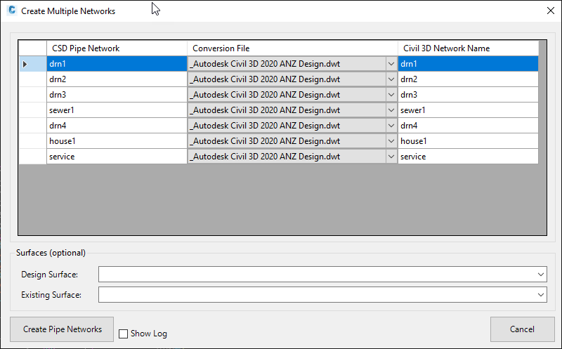
Upon selecting the command, the following form is displayed:
|
|
|
|
Create Multiple Network Table |
Lists all Civil Site Design pipe networks available for export. Pipe networks previously exported are NOT shown. |
|
CSD Pipe Network |
By default all Civil Site Design pipe networks available for export will be listed. To remove a pipe network from the table, simply highlight the row and press Delete on the keyboard. |
|
Conversion File |
Select the conversion file to use for the export of each pipe network (see Network Settings command). |
|
Civil 3D Network Name |
By default, the software will populate this cell with the name of the Civil Site Design pipe network. Change the name as required. |
|
Surfaces (optional) |
Set the Civil 3D surfaces for Profiles to be shown in the Profile Views and referenced to the Civil 3D parts, if set in the conversion file (see Network Settings command). To change the surface(s) see Note 1 below. |
|
Design Surface |
Select the surface to be used for Design. |
|
Existing Surface |
Select the surface to be used for Existing. |
| Create Pipe Networks |
Click to create the all listed Civil 3D Pipe Networks in the drawing and if set, the Alignments and Profiles will also be created. The user will then be prompted to select the insertion point in the drawing for the Profiles Views. |
|
Show Log |
Tick on to generate a Notepad file reporting the status of export. The Notepad file will only be shown if errors are encountered during export. |
|
Cancel |
Exit the form withour exporting any pipe networks. |
Notes:
- To change surfaces used for Design and/or Existing, delete all of the Civil 3D Profiles for each branch alignment in the drawing (the Profile Views do not need to be deleted), then run the Manage Network command and Update the Pipe Network to select different surfaces.
- Pipe Data Source, Profile1 and Profile2 are not managed at the time of creating the profile views - the first pipe network / profile will automatically by assigned. Pipe Data Source, Profile1 and Profile2 need to be manually set by the user post creation of the profile views.