Create/Update Network
| Icon: |
|
| Menu: | Pipes > Create/Update Network |
| Ribbon: | Pipes Tab > Network Panel > Create/Update |
Introduction
This command creates or defines a Pipe Network from a series of connected structures and pipes.
This command will also update a defined Pipe Network, if additional pipes have been added to it or if part of a network was reconnected after being disconnected from using one of the Delete commands.
Note: House Connections or Utility Networks are created when their respective commands are run.
Details
Upon selecting this command, at the Command prompt the user will be asked to "Locate End Structure Required". It is intended for the designer to select the most downstream structure representing the outflow point of the network.
If an end structure of an existing network is selected, the software will update the network to include additional items that have been attached to it and the command will exit. For Drainage Networks users will be required to define the downstream water level, as discussed below.
If an end structure is selected and is not part of a network, the user will be prompted to create a network. Two network types can be created, and the network options will be subject to the type of end structure detected:
Creating a Drainage Network
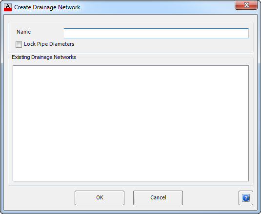
Upon selecting the a Drainage structure to represent the downstream structure of a drainage network the following form will display:
|
|
| Name | Enter a unique name to describe the Pipe Network selected. The name should consist of alpha-numeric characters only and is not case sensitive. |
| Lock Pipe Diameters | Check this option to lock the pipe diameters. When the drainage network is created, all pipe diameter will be kept and the automatic pipe sizing will NOT occur and it is advised that the designer should review the hydraulic performance of the drainage network. |
| Existing Drainage Networks | This is a list of names of defined Pipe Networks of the same type as selected. |
| OK | Select OK to continue. |
| Cancel | Exit the form without creating a Pipe Network. |
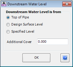
After OK has been clicked and provided the network name entered is unique, the following form is displayed:
 |
|
| Downstream Water is from | Provides a way to set the starting water level for the Hydraulic Grade Line Analysis. |
| Top of Pipe | Use the obvert of the outlet pipe as the starting water level. |
| Design Surface Level | Use the Design Surface Level as the starting water level. |
| Specified Level | Use this to define a known Starting Water Surface Level. When selecting this option enter the level in the box shown. |
| Additional Cover | Type in an additional cover to apply to calculate the outflow pipe elevation. Typically applicable when Design Surface Level selected. |
| OK | Select OK to continue and the Network is created. |
If a network name entered matches one from the list of existing networks displayed, the following warning appears and includes the duplicate network name:
|
|
| OK | Select OK to continue and the user is returned to Create Network form shown previously. |

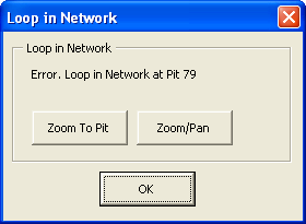
All of the pipes and structures that will make up the network are checked for loops and if one is found, then the network will not be created and the following warning displayed: warning appears and includes the duplicate network name:
 |
|
| Loop in Network | Details the structure at which the loop has been detected. |
| Zoom To Structure | Zoom to the structure in the drawing |
| Zoom/Pan | Provides a way to zoom or pan around in the drawing. Use Mouse Wheel to Zoom/Pan. Press Enter/Esc to Finish. |
| OK | Select OK to continue and the user is returned to drawing. No Network will be created. |
The network will be created (unless a loop was found) and include direction arrows on the pipes showing the downstream direction. Structure labels will also be updated.

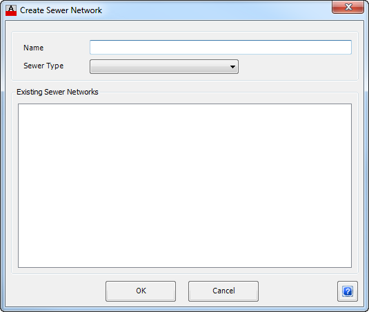
Sewer Network
|
|
| Name | Enter a unique name to describe the Pipe Network selected. The name should consist of alpha-numeric characters only and is not case sensitive. |
| Sewer Type | Select the appropriate type of sewer system. The Sewer Type controls the drop conditions at structures as well as labelling controls. These design Settings are controlled from the Active Network Settings. |
| Existing Sewer Networks | This box provides a list of names of defined Pipe Networks of the same type as selected. |
| OK | Create the Sewer Network and exit. |
| Cancel | Exit the form without creating a Pipe Network. |
If the name entered matches one from the list of existing networks displayed, the following warning appears at the time of creating the network:
|
|
| OK | Select OK to continue and the user is returned to Create Network form shown previously. |
If no Sewer Type has been selected at the time of creating the network the following warning is appears:
|
|
| OK | Select OK to continue and the user is returned to Create Network form shown previously. |

All of the pipes and structures that will make up the network are checked for loops and if one is found, then the network will not be created and the following warning displayed: warning appears and includes the duplicate network name:
|
|
| Loop in Network | Details the structure at which the loop has been detected. |
| Zoom To Structure | Zoom to the structure in the drawing |
| Zoom/Pan | Provides a way to zoom or pan around in the drawing. Use Mouse Wheel to Zoom/Pan. Press Enter/Esc to Finish. |
| OK | Select OK to continue and the user is returned to drawing. No Network will be created. |
The network will be created (unless a loop was found) and include direction arrows on the pipes showing the downstream direction. Structure labels will also be updated. The end (outlet) structure of a defined Pipe Network can be identified by a different structure symbol. The structure symbol displayed can be user defined in the Active Network Settings.