Network Settings
Icon: |
 |
| Ribbon: |
Civil 3D Outputs Tab > Pipe Networks Panel > Network Settings
Pipes Tab > Data Exchange Panel > Manage Networks Dropdown > Network Settings |
Introduction
The Create Network and Multi Create commands export/recreates Civil 3D pipe networks from a Civil Site Design pipe networks.
The Network Settings are a critical component to these commands - it manages the correlation between the Civil Site Design and Civil 3D pipe networks.
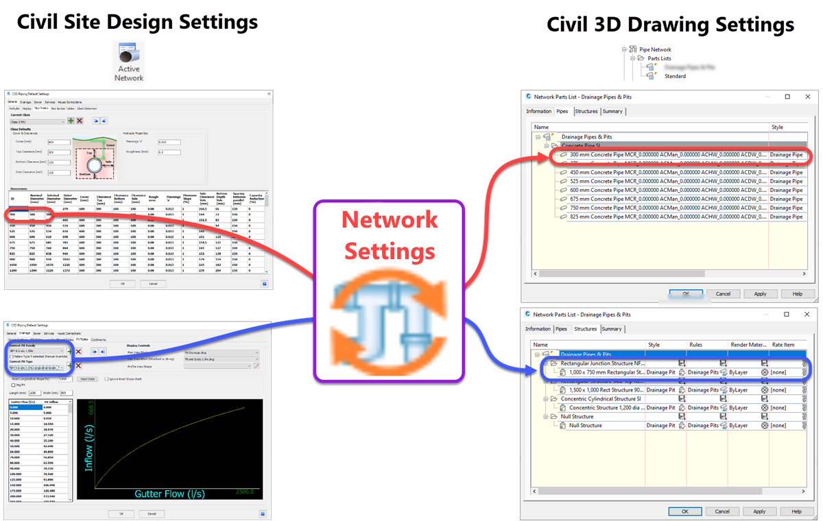
The Network Settings manages the creation of the Civil 3D Pipes and Structure from the Civil Site Design Pipes and
Structures. Using the Network Settings users can:
Network Settings Form - Overview
Civil 3D Pipe Network Catalog and Parts List
It is critical that the current Civil 3D Pipe Network Catalog is the same catalog used to create the Parts List selected in the Network Settings conversion file. If the Pipe Network Catalog does not match the Parts List, then the Part Family and Part Size columns in the Pipes and Structures tabs of the Network Settings form will be blank.
The default Pipe Network Catalog is set based on the version of Civil 3D used, for example:
-
Civil 3D Imperial = US Imperial Pipe Catalog
-
Civil 3D Metric = Metric Pipe Catalog
-
Civil 3D ANZ = ANZ Metric Pipe Catalog
Note: Installing a Civil 3D Country kit may set a country specific Pipe Network Catalog.
In Civil 3D, the Pipe Network Catalog can be set by running the ribbon command Home Tab > Create Design Panel > Create Design Slideout > Set Pipe Network Catalog
Saving Conversion Files
When a Conversion File is created or saved, it is stored in the Civil Site Design Settings folder (see Open Settings Folder command), in a sub-folder named Network Conversion. Each file has the extension .ncf.
Users are encouraged to create multiple Conversion Files to support the different Parts List / Pipe Network Catalogs required.
Details
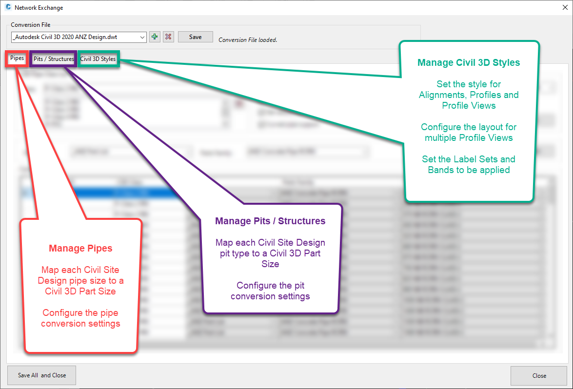
Upon selecting the command, the following form is displayed:
|

|
| Conversion File |
Select the conversion file to edit, as well as create new, delete and save
|
| Conversion File |
Select the conversion file to edit and the form will populate with the data from the conversion file.
|
 |
Click to create a new conversion file. Provide a name for the file.
|
 |
Click to delete the current conversion file. Confirm the delete.
|
| Save |
Click to save the recent changes to the conversion file.
|
|
Pipes Tab
|
Add Civil Site Design Pipe Classes and map them to Civil 3D Part Sizes. Also, configure the settings for pipe export.
|
|
|
|

|
|
CSD Pipe Class List
|
Select and add Civil Site Design Pipe Classes to the conversion file.
|
|
Class Picklist
|
Select the Pipe Class to be added.
|
|
|
Add the selected pipe class to the conversion file. All pipes from the pipe class will be added, applying the selected Parts List and Parts Family and where possible, matched to a Part Size based on the Civil Sight Design pipe size.
|
|
Class List
|
Displays a list of Pipe Classes included in the conversion file.
|
|
|
Remove pipe class selected in Class List from the conversion file (all pipes from pipe class will be removed). Confirm the delete.
|
|
Settings
|
Configure how the export creates the Civil 3D pipes objects.
|
|
Add hydraulic properties
|
Tick on to add the hydraulic properties to the exported pipes.
|
|
Create branch Alignments
|
Tick on to create an Alignment for each branch of the pipe network.
|
|
Set referenced objects
|
Tick on to set the pipe references to the branch alignment and if set, the design surface profile (See Create Network and Multi Create commands).
|
|
Curved pipe support
|
Toggle on to create the pipes with curvature to match the curvature applied to the Civil Site Design pipes (see Set Pipe Radius command).
|
|
Override pipe name
|
Toggle on to name the pipe using the Civil Site Design pipe name (see Network Labelling Settings command).
|
|
Override pipe description
|
Toggle on to apply user-defined descriptions to the pipe (see Set Descriptions below).
|
|
Pipe diameter
|
Select Nominal Diameter or Internal Diameter to specify how the Civil Site Design pipe diameter is translated to Civil 3D. Civil Site Design pipes are defined by the invert of the pipe whereas Civil 3D pipe are defined by the centreline of the pipe.
|
|
/ \ character replace
|
Enter a character to be used to replace / \ in the pipe name.
Civil Site Design pipe names can contain / \ characters which are NOT supported in Civil 3D pipe names.
|
|
Set Descriptions
|
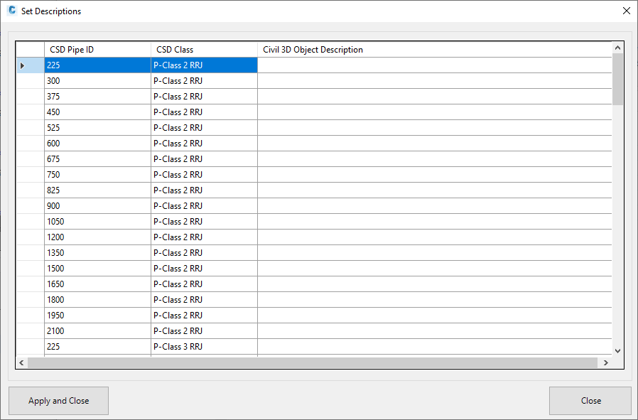
Click to enter the descriptions for the pipes in the conversion file. The following form is displayed:
|
|
|
Descriptions Table
|
Table of all Civil Site Design pipes and corresponding user-definable descriptions.
|
|
CSD Pipe ID
|
List of the pipe sizes available in the conversion file.
|
|
CSD Class
|
List of the pipe class source for the pipe sizes in the conversion file.
|
|
Civil 3D Object Description
|
For each pipe, enter the description to be used when the Civil 3D pipe is created, if set in the conversion file
|
|
Apply and Close
|
Save all data, exit the form and return to the Network Settings form.
|
|
Cancel
|
Exit the form without saving any data and return to the Network Settings form.
|
|
|
|
Specify the Parts List and Parts Family to be used for or Override Selected.
|
|
Parts List
|
Select a parts list.
|
|
Parts Family
|
Select a parts family.
|
|
Override Selected
|
Click to override parts list and parts family for selected pipes in Conversion Table and where possible, matched to a part size based on the Civil Sight Design pipe size.
|
|
Conversion Table
|
Table of all mapped Civil Site Design and Civil 3D pipes in the conversion file. Individual entries can be deleted by selecting one or more rows and pressing the Delete key.
|
|
CSD Pipe ID
|
List of individual pipes in the conversion file.
|
|
CSD Class
|
List of the pipe class source for the pipes in the conversion file.
|
|
Parts List
|
Select the parts list to apply to the selected pipe.
|
| Parts Family |
Select the parts family to apply to the selected pipe. |
| Part Size |
Select the part size to apply to the selected pipe. |
|
|
Structures Tab
|
Add Civil Site Design Structure Families and map them to Civil 3D Part Sizes. Also, configure the settings for
structure export.
|
|
|
|

|
|
CSD Structure Family List
|
Select and add Civil Site Design Structure Families to the conversion file.
|
|
Family Picklist
|
Select the Structure Family to be added.
|
|
|
Add the selected structure family to the conversion file. All structure types from the
structure family will be added, applying the selected Parts List and Parts Family.
|
|
Family List
|
Displays a list of Structure Families included in the conversion file.
|
|
|
Remove structure family selected in Family List from the conversion file (all
structure types from structure family will be removed). Confirm the delete.
|
|
Settings
|
Configure how the export creates the Civil 3D structure objects.
|
|
Override structure name
|
Toggle on to name the structure using the Civil Site Design structure name (see Network Labelling Settings command).
|
|
Override structure description
|
Toggle on to apply user-defined descriptions to the structure (see Set Descriptions below).
|
|
Set referenced objects
|
Tick on to set the structure references to the branch alignment and if set, the design surface profile (See Create Network and Multi Create commands).
|
|
/ \ character replace
|
Enter a character to be used to replace / \ in the structure name.
Civil Site Design structure names can contain / \ characters which are NOT supported in Civil 3D structure names.
|
|
Set Descriptions
|
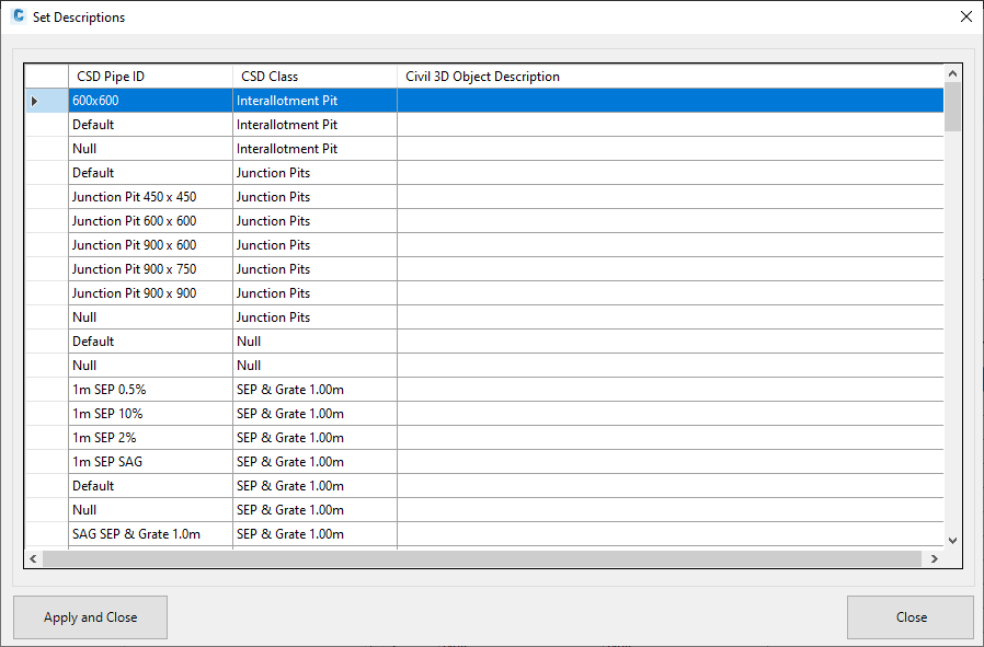
Click to enter the descriptions for the structure types in the conversion file. The following form is displayed:
|
|
|
Descriptions Table
|
List of Civil Site Design structure types and corresponding user-definable descriptions.
|
|
CSD Pipe ID
|
List of the structure types available in the conversion file.
|
|
CSD Class
|
List of structure family source for structure types in the conversion file.
|
|
Civil 3D Object Description
|
For each structure type, enter the description to be used when the Civil 3D structure is created, if set in the conversion file.
|
|
Apply and Close
|
Save all data, exit the form and return to the Network Settings form.
|
|
Cancel
|
Exit the form without saving any data and return to the Network Settings form.
|
|
|
|
Specify the Parts List and Parts Family to be used for or Override Selected.
|
|
Parts List
|
Select a parts list.
|
|
Parts Family
|
Select a parts family.
|
|
Override Selected
|
Click to override parts list and parts family for selected structure types in Conversion Table.
|
|
Conversion Table
|
Table of all mapped Civil Site Design and Civil 3D structure types in the conversion file. Individual entries can be deleted by selecting one or more rows and pressing the Delete key.
|
|
CSD Structure Type
|
List of individual structure types in the conversion file.
|
|
CSD Structure Family
|
List of the structure family source for the structure types in the conversion file.
|
|
Parts List
|
Select the parts list to apply to the selected structure type.
|
| Parts Family |
Select the parts family to apply to the selected
structure type. |
| Part Size |
Select the part size to apply to the selected
structure type. |
|
|
Civil 3D Styles Tab
|
Select the styles, band sets and label sets for Alignments, Profiles and Profile Views created as part of the Pipe Network export. Also, enter the spacing for the Profile View placement in the drawing.
|
|
|
|

|
|
Alignment
|
Select the Style, Label Set and Site for Alignments created for branches (if Create branch alignments toggled on in Pipes Tab).
|
|
Style
|
Select the alignment style.
|
|
Label Set
|
Select the alignment label set.
|
|
Site
|
Toggle this on to create branch alignments in a named site.
|
|
Name
|
Enter the name on the site to be created.
|
|
Profile View
|
Select the Style and Band Set for Profile Views created from branch alignments (if Create branch alignments toggled on in Pipes Tab).
|
|
Style
|
Select the profile view style.
|
|
Band Set
|
Select the profile view band set.
|
|
Layout
|
Define the how the Profile Views are placed in the drawing (see Profile View Layout below). |
|
Max Rows
|
Enter the maximum number of rows.
|
|
Row Spacing
|
Enter the row spacing.
|
|
Column Spacing
|
Enter the column spacing.
|
|
Design Profile Style
|
Select the Style and Label Set for Design profiles created from branch alignments (if Create branch alignments toggled on in Pipes Tab).
|
|
Style
|
Select the profile style.
|
|
Label Set
|
Select the profile label set.
|
|
Existing Profile Style
|
Select the Style and Label Set for Existing profiles created from branch alignments (if Create branch alignments toggled on in Pipes Tab).
|
|
Style
|
Select the profile style.
|
|
Label Set
|
Select the profile label set.
|
|
|
Save All and Close
|
Save all data and exit the form.
|
|
Close
|
Exit the form without saving any data.
|
Profile View Layout Details
The Layout settings and how they impact the placement of the Profile Views in the drawing are:
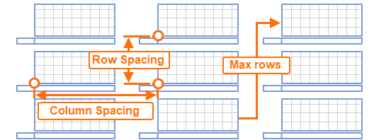
The spacing is measured between Profile View insertion points and the values are in the units of the drawing.
These settings are used for initial profile view placement in the drawing, once created, the profile view locations will NOT be altered. It is anticipated that the users will arrange profile view as required.
The objects within the Profile Views will be updated as changes are made to the Civil Site Design pipe network (see Manage Networks command) or if the Sync Networks command is run.