Edit Pit Properties
| Icon: | |
| Menu: | CSD Pipes > Edit > Edit Pit Properties |
| Ribbon: | Pipes Tab > Edit Panel > Edit Pit Properties |
Introduction
This command provides a way to edit the properties of a pit.
These properties include Pit Classification, Selected Road, Pit Location, Top of Pit Level, Hydraulic Design Level, Pipe Levels for Pit and Bottom of Pit Level.
Details
Upon selecting this command, at the Command prompt the user will be asked to "Locate Pit to Edit".
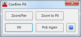
When a pit is selected, a glyph will appear at the pit and the following form is displayed (unless disabled in the Active Network Settings). Should a point be picked not within a specified range, a warning message will be displayed and press OK to continue and select a point closer to the require pit.
 |
|
Zoom/Pan |
Provides a way to zoom or pan around in the drawing. Use Mouse Wheel to Zoom/Pan. Press Enter/Esc to Finish. |
Zoom to Pit |
Will zoom to the selected pit, so that it fits within the screen. |
OK |
Select OK to continue. |
Pick Again |
Provides the option to select a different pit, if the highlighted pit is incorrect. |
After a pit is selected the following form is displayed (the controls may vary pending the options selected):
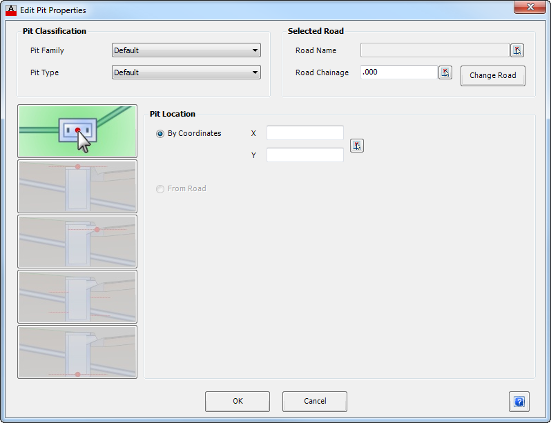 The general controls of the form are as follows: |
|
| Pit Classification | This panel is where the Family and Type of Pit can be changed. |
| Pit Family | A drop down box provides a list of all available Pit Families which can be selected. Select the appropriate Family. |
| Pit Type | A drop down box provides a list of available Pit Type from the Pit Family selected above. Select the appropriate Pit Type. Note: The user can create Pit Families and Pit Type for a specific project. These are defined in CSD Pipes > Settings > Active Network Settings. |
| Selected Road | This panel provides information on the relationship between the pit and a road. A different road can also be selected. |
| Road Name | Displays the Road Name to provide a relative chainage reference. The selected Road Name enables the software to extract other relevant information that is needed for calculation and reporting purposes. Use  to select the Road Alignment directly from the drawing. to select the Road Alignment directly from the drawing. |
| Road Chainage | Displays the Road Chainage for the selected Road Name, taken perpendicular to the centreline. The chainage can be entered directly into the box provided or use to select the Road Chainage directly from the drawing. |
| Change Road | This button is used to select a different Road Name for the pit to reference to. When this button is pressed a new form appears with a list of defined Roads that can be used. Caution: If this option is selected the pit location may change which will alter the defined pipe network. |
This form has five control options accessed by clicking on each of the icons represented on the left side of the form. Each selection changes the display information in the frame to the right of the icons. Control options are as follows (click on one of the links below to navigate directly to that control):
|
|
OK |
Apply and exit. |
Cancel |
Exit the form without deleting any data. |
Pit Location |
|
|
|
| Pit Location | This controls the plan position of the pit. |
| By Co-ordinates | Toggle this option on to control the Pit Location by co-ordinates. Inputs are: |
| X | Type in the easting (X) co-ordinate |
| Y | Type in the northing (Y) co-ordinate |
| Select from Drawing |
Click to select a position for the pit from the drawing. The X and Y cells will be populated from the selected location in the drawing. |
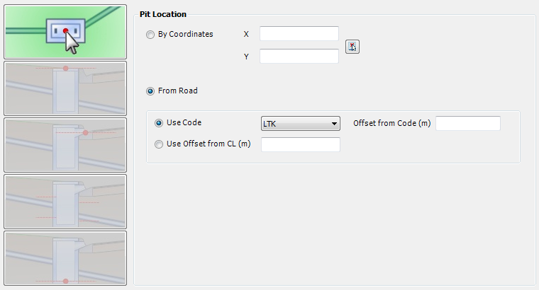
| From Road | Toggle this option on to set the Pit Location from a Selected Road (indicated at the top of this form). Note: This option links a pit to the Selected Road. This link is maintained and the pit will update the horizontal position based on changes to the Road. |
| Use Code | Toggle option to set the pit position based on a Road Code. Select the appropriate Road/String Code to control the Pit Location - the list is populated based on the Road/String selected. |
| Offset from Code (m) | Enter a value, in metres, to offset the pit position from the selected code. The offset is taken perpendicular to the Road centreline at the nominated Road Chainage. A positive value will shift the pit location outwards from the Road centreline. |
| Use Offset from CL (m) | Toggle option to set the pit position as an offset from the Road centreline. Enter, in metres, an offset value measured from the road centreline for the pit location. The offset is taken perpendicular to the Road centreline at the nominated Road Chainage. The entered offset follows the standard cross section convention of negative to the left and positive to the right, in the direction of increasing chainages. |

Top of Pit Level |
|
|
|
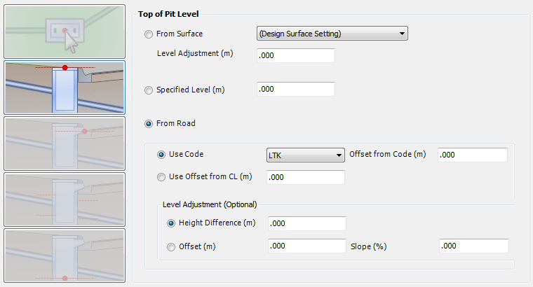
| Top of Pit Level | This controls the Top of Pit Level. |
| From Surface | Toggle this option to set the top of pit level from a Surface. Select a Surface from the drop down list box. Note: The top of pit level will adjust as the nominated Surface is adjusted. If the surface is deleted pits will be located at elevation zero. |
| Level Adjustment (m) | If From Surface is select, type in a value to raise (positive value) or lower (negative value) the top of pit level relative to the nominated surface. |
| Specified Level (m) | Toggle this option to set a level for the top of pit. Type in a value in metres. |
| From Road | Toggle this option on to set the Top of Pit level from a Selected Road (indicated at the top of this form). Note: This option links a pit to the Selected Road. This link is maintained and the pit will update the top of pit levels based on changes to the Road. |
| Use Code | Toggle option to set the top of pit level based on a Road Code. Select the appropriate Road/String Code to control the Pit Location - the list is populated based on the Road/String selected. |
| Offset from Code (m) | Optional additional offset from the Code, measured perpendicular to the road Centreline and with positive values offsetting outwards from the centreline alignment. The Road design model levels will be extracted at this point and used for the top of pit levels. |
| Use Offset from CL (m) | Toggle option to set the top of pit levels from the Road model elevations at an offset from the Road centreline. Enter, in metres, an offset value measured from the road centreline. The offset is taken perpendicular to the Road centreline at the nominated Road Chainage. The entered offset follows the standard cross section convention of negative to the left and positive to the right, in the direction of increasing chainages. |
| Level Adjustment (Optional) | An optional Level Adjustment can be applied to the level obtained from either Use Code or Offset from CL. Two (2) methods are available: |
| Height Difference | Toggle this option to enable raising/lowering the top of pit level. Enter the relative height, in metres, to be applied. |
| Offset (m) | Toggle this option to apply a height difference based on an additional offset and slope. Enter the required Offset in metres and then required the slope in percent. |
| Slope (%) | Enter the required Slope in percent. |
Hydraulic Design Level |
|
|
|
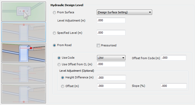
Hydraulic Design Level |
This controls the Hydraulic Design Level property. This is the water surcharge level from the pit, which may be required for bypass flows to another pit. |
From Surface |
Toggle this option to set the hydraulic design level from a Surface. Select a Surface from the drop down list box. Note: The top of pit level will adjust as the nominated Surface is adjusted. If the surface is deleted pits will be located at elevation zero. |
| Level Adjustment (m) | If From Surface is select, type in a value to raise (positive value) or lower (negative value) the hydraulic design level relative to the nominated surface. |
| Specified Level (m) | Toggle this option to set a level for the hydraulic design level. Type in a value in metres. |
| Pressurised | By default, the HGL is restored to the top of pit level at the downstream end of the pit, in the event that the incoming HGL is above the pit at the upstream end. If Pressurised is ticked on, the HGL can be maintained above the surface level through the pit and into the downstream pipe. |
| From Road | Toggle this option on to set the Hydraulic Design Level from a Selected Road (indicated at the top of this form). Note: This option links a pit to the Selected Road. This link is maintained and the pit will update the hydraulic design levels levels based on changes to the Road. |
| Use Code | Toggle option to set the hydraulic design level based on a Road Code. Select the appropriate Road/String Code to control the Pit Location - the list is populated based on the Road/String selected. |
| Offset from Code (m) | Optional additional offset from the Code, measured perpendicular to the road Centreline and with positive values offsetting outwards from the centreline alignment. The Road design model levels will be extracted at this point and used for the hydraulic design levels. |
| Use Offset from CL (m) | Toggle option to set the hydraulic design levels from the Road model elevations at an offset from the Road centreline. Enter, in metres, an offset value measured from the road centreline. The offset is taken perpendicular to the Road centreline at the nominated Road Chainage. The entered offset follows the standard cross section convention of negative to the left and positive to the right, in the direction of increasing chainages. |
| Level Adjustment (Optional) | An optional Level Adjustment can be applied to the level obtained from either Use Code or Offset from CL. Two methods are available: |
| Height Difference | Toggle this option to enable raising/lowering the hydraulic design level. Enter the relative height, in metres, to be applied. |
| Offset (m) | Toggle this option to apply a height difference based on an additional offset and slope. Enter the required Offset in metres and then required the slope in percent. |
| Slope (%) | Enter the required Slope in percent. |
Pipe Levels for Pit |
|
 |
|
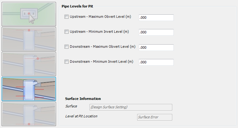
| Pipe Levels for Pit | This provides control for an envelope on levels for pipes in the pit. |
| Upstream - Maximum Obvert Level | If selected, this will ensure the Upstream pipe obvert does not rise above the nominated level. |
| Upstream - Minimum Invert Level | If selected, this will ensure the Upstream pipe invert does not drop below the nominated level. |
| Downstream - Maximum Obvert Level | If selected, this will ensure the Downstream pipe obvert does not rise above the nominated level. |
| Downstream - Minimum Invert Level | If selected, this will ensure the Downstream pipe invert does not drop below the nominated level. |
| Surface Information | This is display information describing the applied surface and the calculated level. It is provided to assist in determining appropriate pipe level controls. |
Bottom of Pit Level |
|
 |
|
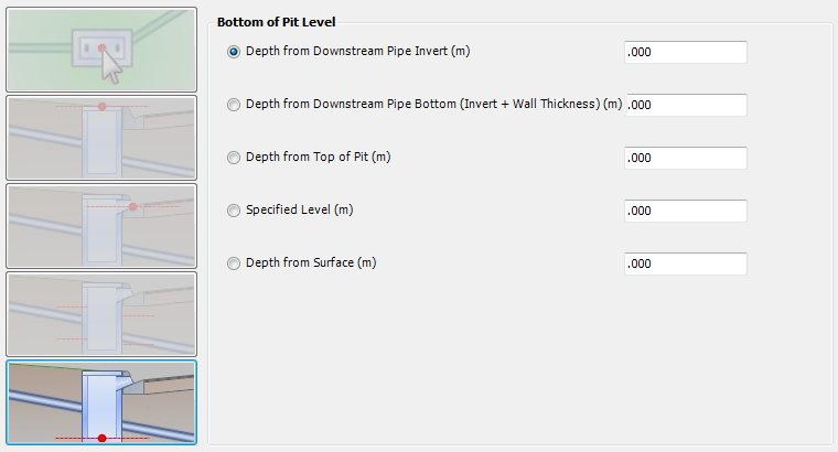
| Bottom of Pit Level | By default, the bottom of pit level is determined from the invert level of the downstream pipe. This enables full control over the Bottom of Pit Level. |
| Depth from Downstream Pipe Invert (m) | Toggle this option on to set the Bottom of Pit Level based on the Downstream Pipe Invert. Type in the additional Depth required. |
| Depth from Downstream Pipe Bottom (m) | Toggle this option on to set the Bottom of Pit Level based on the Downstream Pipe Bottom (Invert + Wall Thickness). Type in the additional Depth required. |
| Depth from Top of Pit (m) | Toggle this option on to set the Bottom of Pit Level as a fixed depth from the top of pit. Type in the depth required. This option might be used for pre-cast pits and risers. Note: this control option will not prevent the pipe levels being set below the bottom of pit levels. |
| Specified Level (m) | Toggle on this option to set a specified level for the bottom of pit. Type in the level in metres. Note: this control option will not prevent the pipe levels being set below the bottom of pit levels |
| Depth from Surface (m) | Toggle on this option to set the Bottom of Pit Level as a depth below the the Surface Level (the software uses the Design Surface as defined in the Active Network Settings). Note: this control option will not prevent the pipe levels being set below the bottom of pit levels. |