Survey String Settings
Icon: |
Introduction
The Survey String Settings controls whether a GOGO Point is connected with linework and how the points are connected: as 2D polylines, as 3D polylines or as Breaklines for the surface.
By default, linework is created between Points as straight lines, using the Point 'code' and Survey String 'number' (eg: CL1, with CL being the 'code' and 1 being the 'Survey String number') from the Point Description. The Point Description encompasses the Code, Survey String number and any Parameter applied.
A Point can describe two features for the same point, by using a space delimiter between the feature descriptions. (eg: a description of "EB1 FP1" could enable two Survey Strings to pass through that Point for the EB1 (edge of bitumen) and the FP1 (footpath) point descriptions)
The Survey String Settings manages the linework based on the point Description (the Code that describes the point feature). Via the Survey String Settings users can control, per Code:
Whether to use it as a surface breakline
To create 2D linework connecting the COGO Points
To create 3D linework connecting the Points
Each list of descriptions with their linework actions is grouped into what is called a Survey String Table (String Set Table).
Details
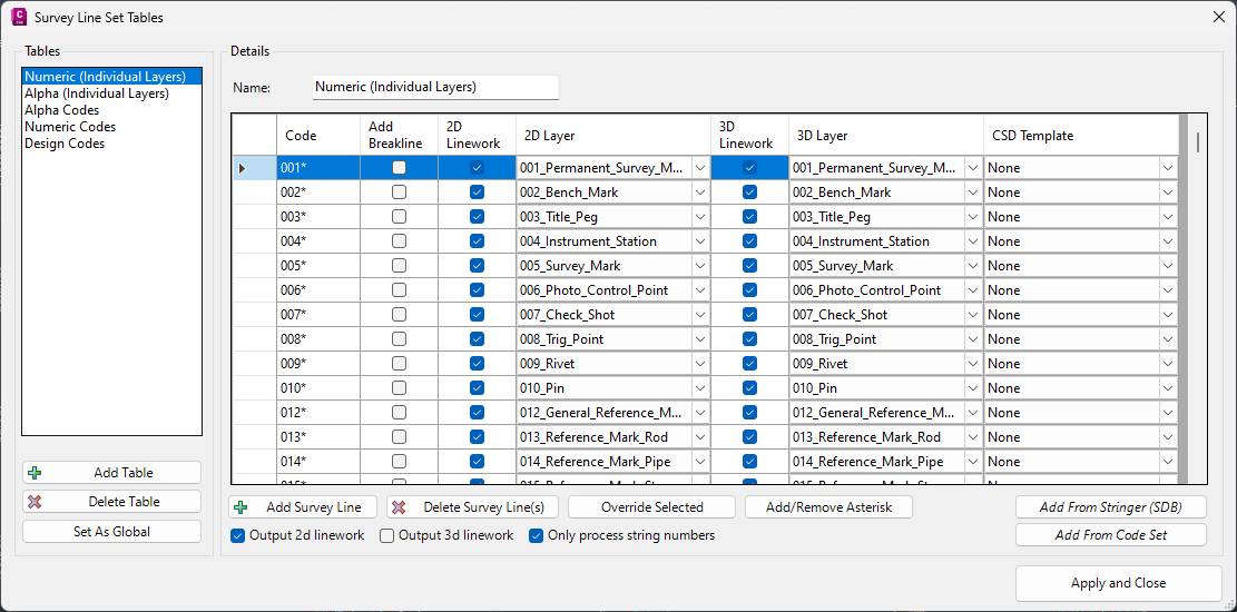
Upon selecting the command the following form is displayed:
|
|||||||||||||||||||
Tables |
This lists all Survey String Tables. Each Table details how Points are connected, using their Descriptions | ||||||||||||||||||
[List of Tables] |
List of created Survey String Tables. Click on a Table to set it for editing on the RHS of the form | ||||||||||||||||||
Add Table |
Click to add a new Survey String Table. A default Name will be assigned and this will be set on the RHS of the form for editing | ||||||||||||||||||
Delete Table |
Deletes the highlighted Table in the Table list | ||||||||||||||||||
Set as Global |
Click
to set the selected table to be included in the 'Global' Table
list. This will overwrite the current Table settings
in the CSD
Settings folder and replace with the ones established here. A confirmation message will display to set these as the global/default - yes to overwrite or no to retain the current default Table properties. |
||||||||||||||||||
Details |
The Right Hand Side (RHS) of the form provides functionality to edit the selected Table | ||||||||||||||||||
| Name | Type in a name for the Survey String Table. As a name is typed it will edit the saved Table name | ||||||||||||||||||
Survey String List |
Table of inputs to manage the Codes and how they are connected with Survey Stringwork. | ||||||||||||||||||
Code |
Type
in a Code to make Survey Stringwork connections and for breaklines. The Code is any portion of a point description. Use a Wildcard (*) to allow for numeric inputs (Survey String numbers) and parameters to be included in the Point Description |
||||||||||||||||||
Add Breakline |
Tick on for the code linework to be treated as a breakline | ||||||||||||||||||
2D Linework |
Tick on for the code linework to be created as a 2D polyline in the drawing | ||||||||||||||||||
2D Layer |
Select the layer to draw the 2D polylines | ||||||||||||||||||
3D Linework |
Tick on for the code linework to be created as a 3D polyline in the drawing | ||||||||||||||||||
3D Layer |
Select the layer to draw the 3D polylines | ||||||||||||||||||
CSD Template |
Select a Civil Site Design template to apply to the Survey String. The Codes from the Template will be applied to the calculated offset linework for rendering in Model Viewer. The Template generated linework will be drawn on the 2D Linework and 3D Linework settings layers for the Code. Breaklines will be added from the Template generated linework if Add Breakline is ticked on. | ||||||||||||||||||
Add Survey String |
Add a new blank entry in the list. | ||||||||||||||||||
| Delete Survey String(s) | Click to delete highlighted entry/ies in the list (shift+left mouse and ctrl+left mouse can be used to make multiple selections) | ||||||||||||||||||
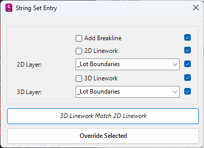
| Override Selected |
Override the Breakline, 2D/3D layers and linework values for highlighted codes. Upon running this command the following form is displayed:
|
||||||||||||||||||
| Add/Remove Asterisk | Add or Remove the trailing * (asterisk) from highlighted codes in list. | ||||||||||||||||||
| Only process String numbers | When
unticked, any matching Point Descriptions will be connected with
a Survey String (eg: points with description CL). If ticked on, only Point Descriptions that also include a Survey String (String) number at the end will be connected with a Survey String (eg: points with description CL1, CL2 etc would be connected, but points with description CL would not). Note: If Survey Strings have already been created, this tick box change will not remove these Survey String connections. They would need to be removed in the Survey String Manager. |
||||||||||||||||||
| Output 2D polylines | If unticked 2D polylines will not be created in the drawing for the survey string (even if ticked on in the list to be added). | ||||||||||||||||||
| Output 3D polylines | If unticked 3D polylines will not be created in the drawing for the survey string (even if ticked on in the list to be added). | ||||||||||||||||||
| Only process String numbers | When
unticked, any matching Point Descriptions will be connected with
a Survey String (eg: points with description CL). If ticked on, only Point Descriptions that also include a Survey String (String) number at the end will be connected with a Survey String (eg: points with description CL1, CL2 etc would be connected, but points with description CL would not). Note: If Survey Strings have already been created, this tick box change will not remove these Survey String connections. They would need to be removed in the Survey String Manager. |
||||||||||||||||||
| Add from Stringer (SDB) | This
will append to the Table using entries contained in a Stringer
Topo .SDB file to the current Table. After clicking,
a form will display to select the .sdb file. Note: Stringer Topo for AutoCAD/BricsCAD creates and stores stringing information in a file with extension .sdb. |
||||||||||||||||||
| Add from Code Set | This will append to the Table using any created Survey String Settings (Points). | ||||||||||||||||||
| Apply and Close | Close the form and save changes. | ||||||||||||||||||