Create Grading
Introduction
Grading Strings are the same as other Strings, with the
following differences:
-
Grading Strings are created directly from polylines
-
The horizontal, vertical and cross sectional geometry is updated automatically when the polyline is edited (grip edited or otherwise)
-
Grading Strings contain cross sections that automatically trim internal bends. External bends can apply either a chamfer, radial or mitred join. Corner trimming is limited to adjacent segments through the bend, and updates from any vertical or horizontal edit
-
Grading Strings can be edited vertically via a grid view editing window - IP's created or edited in the grid view automatically update the Vertical Grading Editor, and vice versa
-
Grading String surfaces can be set to infill internal areas
Grading Strings can be used for various design tasks, such as: lot grading, detention basins, building pads, retaining walls and car parks.
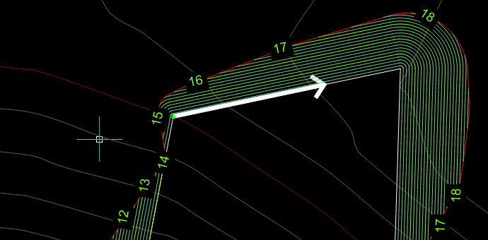
Once a polyline is selected for a Grading, a directional
arrow is drawn to show the direction of the grading calculations.
Initially, the polyline direction is used for the grading direction.
It is intended for multiple Grading Strings to be built into surfaces using the
 Model Builder command, to be combined with other grading strings and other design strings.
In the case that the grading forms part of a broader collection of strings
forming an overall design surface, it may be preferred to tick on the No Surface
option to not create a surface from the grading.
Model Builder command, to be combined with other grading strings and other design strings.
In the case that the grading forms part of a broader collection of strings
forming an overall design surface, it may be preferred to tick on the No Surface
option to not create a surface from the grading.
Any 2d polyline on any layer can be used for a grading. Use this command to convert a 2D polyline into a Grading String.
This form contains three (for Civil 3D users) or four tabs:
-
Create Grading: You use this tab to create the grading by applying a Template and starting elevation, amongst other controls.
-
Vertical Grading: This is the grid view of the vertical design, and includes buttons to automate the addition of vertical IP's based on different horizontal and vertical geometry, as well as tools to raise/lower IP's in the view.
-
Breaklines (excluding Civil 3D platform): This tab provides functionality for the designer to force breaklines from one side the grading to another. Breaklines only form where they cross the grading string and are intended for designs such as lot grading, where the designer is forcing triangulation between the frontage and rear-age of the lots.
-
Volumes: This provides surface comparison volume information
between two Civil Site Design surfaces.
Breakline Notes: Overlapping breakline entries is not recommended as unexpected triangulation results can occur. When breaklines overlap, elevations will be taken from one of the two breaklines. Breaklines do not need to share any elevations where they cross so triangulation results can be undesirable in overlap situations.
Notes:
Use the
 Create/Edit Section (Create/Edit Template) command to create cross sections to apply around the Grading. After creating the Grading, opening the Design Data Form from the Vertical Grading Editor form for the string will enable editing of the cross section shape along the string length
Use the
 Paste
Surfaces command to create combined TIN surface/s. This
can then be used as a base surface for further design, and to create a
single composite surface of designed and existing parts.
Paste
Surfaces command to create combined TIN surface/s. This
can then be used as a base surface for further design, and to create a
single composite surface of designed and existing parts.
Use the
Model Builder command to construct user defined surface models combining any and all Strings and codes, with user control over all code trimming for the surface.
When editing in the Vertical Grading tab, a marker will display at the location of vertical IP highlighted in the list of IP's. The marker displayed is managed in the
CSD Settings folder - a drawing file located in the Settings folder named GradingMarkerActive.dwg is applied. Users can edit this .dwg to change the marker.
Grading and Model Viewer
It is common to use multiple Grading Strings in the construction
of an overall surface. In Model Viewer, rendering is applied to the
triangles using the Codes assigned to each triangle edge. These Codes come
from the String cross sections.
Typically, the code C.L. is used to represent the centreline
of a road and is rendered accordingly in Model Viewer. It may be
advantageous if the centreline code of Grading is not defined with the code
of C.L. to prevent unexpected material rendering results.
If the option is used, users can opt to have a prefix
section, main replacement name section and suffix section in the Code.
Format is: prefix@main$suffix
Volumes Tab in Civil 3D
For Civil 3D users, the Volumes tab will not operate unless both
the base surface and the grading surface are Civil Site Design surfaces (not
Civil 3D surfaces). Users have two options for obtaining volume
information between a grading and base surface:
-
Use the
Civil 3D Surfaces command to create a Civil 3D surface from
the grading and then use Civil 3D surface volume tools to compare
-
Use the
C3D to CSD
Surface command to convert the Civil 3D 'base' surface into
a Civil Site Design surface equivalent. Once that is done it can
be used as the base and the volumes tab will work as expected.
Details
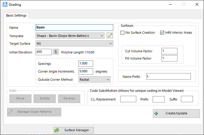
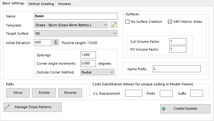
Upon selecting the command and graphically selecting a polyline in the drawing, the following form is displayed:
|
|
| Basic Settings Tab |
This tab is used for creating Grading Strings and making edits such as changing the Target Surface (surface for batter projections) |
|
|
|
| Grading Controls |
Sets out the grading string controls to apply when Create/Update is selected |
| Name |
Type in a name for the Grading String. |
| Template |
Assign a cross section Template to apply around the Grading String. |
 Edit Template Edit Template |
This button opens the Create/Edit Section form. Inputs are as per the  Create/Edit Section command. Create/Edit Section command. |
| Target Surface |
Surface to project batters (daylight) to. Batter positions are calculated at sample intervals along the grading string. |
| Initial Elevation |
Type in an initial elevation for the Grading String. When the Create/Update button is selected, this value is applied to the string. |
 Type Type |
Select a location on screen to input the elevation. |
| Polyline Length |
Non-editable field detailing the total length of
the selected polyline. |
| Spacings |
Sets the sampling of sections along the grading.
All geometry points of the polyline will be sampled. |
| Corner Angle Increments |
Angle (in degrees) between sampled sections through an external bend that does not include a horizontal curve. |
| Outside Corner Method |
Set how to treat external bends that don't include a horizontal curve. Options:
- Radial: Radial 'fan' calculated around the bend, using the Angle Increment at Corners value
- Mitre: Extends the offset codes straight out from their last calculated positions before the bend (using the incoming and outgoing tangent directions) until they meet
- Chamfer: Creates a chamfer (line) running through the bend
- Clover: Creates a clover leaf shape calculating offsets |
| Surfaces |
|
| No Surface
Creation |
If ticked, a surface will not be created directly
from the Grading String sections. |
| Infill Interior Areas |
If the Grading String (polyline) is closed, ticking this on will include the internal area in the volume calculation report generated from the Grading form. |
| Cut Volume Factor |
Set to 1 for no change - allows for adjustments to the calculated cut volumes. Applied in the in the volume calculation report generated from the Grading form. |
| Fill Volume Factor |
Set to 1 for no change - allows for adjustments to the calculated fill volumes. Applied in the in the volume calculation report generated from the Grading form. |
| Name Prefix |
Adds a prefix to the Name assigned for the string.
Useful for grouping by name. |
| Edits |
|
| Move |
Select a new position for the grading. This
relocates the polyline and recalculates the grading |
| Rotate |
Select a new rotation for the grading. This
rotates the polyline and recalculates the grading. |
| Reverse |
Reverse the polyline (and grading) direction |
| Surface
Code Substitution |
This allows for replacement of
the C.L. code with a unique code, to improve material rendering assignment in
Model Viewer |
| C.L. Replacement |
Type in a Code to apply instead of 'C.L.' |
| Prefix |
Add a prefix to the Code. This is separated
from the main C.L. Replacement input by a @ |
| Reverse |
Add a suffix to the Code. This is separated from
the main C.L. Replacement input by a $ |
| Create/Update |
Click to create or update the Grading String. Changes to Template or Initial Elevation will be applied upon updating. |
|
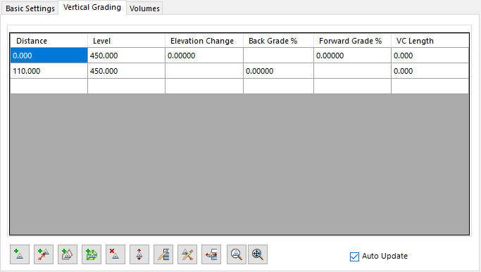
| Vertical Grading Tab |
This tab is used for creating Grading Strings and making edits such as changing the Target Surface (surface for batter projections) |
| |
|
| Grid View |
Displays the vertical design in a grid view. As each item is clicked on a marker is displayed in plan at the vertical IP location. List items are described below |
| Distance |
chainage along grading string for IP location |
| Level (Elevation) |
Elevation of the IP |
| Elevation Change |
Elevation difference from the current IP to next IP |
| Back Grade % |
Grade from the current IP to the previous IP |
| Forward Grade % |
Grade from the current IP to the next IP |
| VC Length |
Type in a vertical curve length to apply at the IP. Leave at .001 for no Vertical Curve to be applied |
 Add IP by selection Add IP by selection |
Pick a location in the drawing along the grading string - an IP will be added at that location |
 Add IP by
Reference Add IP by
Reference |
Adds a vertical IP from a reference point selected
in the drawing.
At the command prompt, select a location in the drawing to use as a REFERENCE
point for elevations to a new IP.
The following form will display:
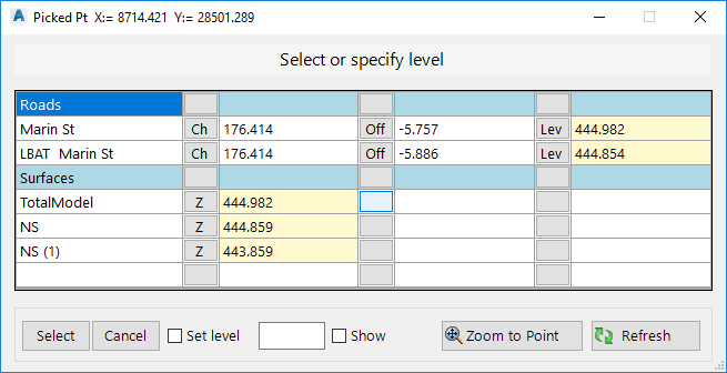
|
|
List View of Elevations at the location selected. |
| Objects Found |
Lists Surfaces and Strings located in proximity to
the selected point |
| Chainage/Station, Offset, Elevation |
Other columns describe the information type (Ch for
chainage/station, Off for offset from alignment, Lev for level/elevation, z for
surface elevation).
Users must select an elevation to apply (highlighted with a yellow background) |
| Select |
Apply the selected elevation to the x,y position
selected. This sets the Reference Point x,y,z position |
| Cancel |
Exit the command without creating a new IP |
| Set Level |
Tick on to override the elevation to a user
specified value. Type in a value in the cell provided |
| Show |
Tick on to draw text for the elevation of the
Reference Point |
| Zoom to Point |
Zoom to the selected x,y point
|
| Refresh |
Refresh enquiry tool and drawing display |
Upon clicking Select, the user is prompted ('Pick point on String for new
elevation) to graphically locate the location along the string C.L. to create
the new IP. Upon selection the following form displays:
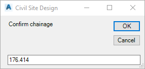
|
| Chainage/Station |
Confirm the location along the string to create the
new IP. Overtype as required |
| OK |
Proceed to next step |
| Cancel |
Cancel the command |
Upon clicking OK, the user is prompted to select a grade/slope to apply from the
REFERENCE Point to the selected location on the string.
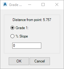
|
| Grade 1: or % Slope |
Toggle to select the method for setting the final
elevation of the IP. Input the value required (note: a Grade of 1:0 is not
allowed) |
| OK |
Create a new IP |
| Cancel |
Cancel the command |
|
 Add IP's at horizontal geometry Add IP's at horizontal geometry |
Adds vertical IP's at horizontal geometry points along the polyline. The following form will display:
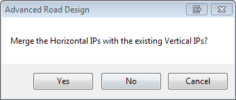
|
| Yes |
Adds extra IP's at the horizontal geometry points, keeping the existing design IP's |
| No |
Replaces the current vertical design with IP's only at the horizontal geometry points. |
| Cancel |
Do not add IP's at horizontal geometry points |
|
 Add IP's to Match Surface Levels at Selected Sections Add IP's to Match Surface Levels at Selected Sections |
Creates IP's at all sampled sections around the grading string and sets the elevation of the IP's to match the surface |
 Delete IP Delete IP |
Deletes the first highlighted IP in the grid view |
 Raise/Lower All IP's Raise/Lower All IP's |
Raises/Lowers all IP's by a user defined amount. Inputs are as follows:
|
| Input |
Type in an elevation change (positive up, negative down) |
| OK |
Apply elevation change |
| Cancel |
Do not apply and exit form |
|
 Edit Multiple IP's
 |
Select multiple rows in a column to edit that
column. Options are:
bbcvb bbcvb bbcvb
|
Level column cells are highlighted |
|
| Input |
Type in an elevation change (positive up, negative down)
to apply to all highlighted cells |
| OK |
Apply elevation change |
| Cancel |
Do not apply and exit form |
|
Grade % cells are highlighted |
|
| Input |
Type in a single grade (%) to apply to all
highlighted cells |
| OK |
Apply grade (%) change |
| Cancel |
Do not apply and exit form |
|
VC Length column cells are highlighted |
|
| Input |
Type in a VC length to apply to all highlighted
cells. VC length will be truncated to prevent overlapping IP's or other
VC's as required. |
| OK |
Apply elevation change |
| Cancel |
Do not apply and exit form |
|
 Edit Elevtion by Reference
 |
This is an EDIT command. Before running this
command, users must first highlight the IP to edit, then select this command.
At the command prompt, select a location in the drawing to use as a REFERENCE
point for elevations to the selected IP. A graphic line shows the position
of the current IP and the mouse location of the reference point. Click to
select the reference point location.
The following form will display:
|
|
List View of Elevations at the location selected. |
| Objects Found |
Lists Surfaces and Strings located in proximity to
the selected point |
| Chainage/Station, Offset, Elevation |
Other columns describe the information type (Ch for
chainage/station, Off for offset from alignment, Lev for level/elevation, z for
surface elevation).
Users must select an elevation to apply (highlighted with a yellow background) |
| Select |
Apply the selected elevation to the x,y position
selected. This sets the Reference Point x,y,z position |
| Cancel |
Exit the command without creating a new IP |
| Set Level |
Tick on to override the elevation to a user
specified value. Type in a value in the cell provided |
| Show |
Tick on to draw text for the elevation of the
Reference Point |
| Zoom to Point |
Zoom to the selected x,y point
|
| Refresh |
Refresh enquiry tool and drawing display |
Upon clicking Select, the user is prompted ('Pick point on String for new
elevation) to graphically locate the location along the string C.L. to create
the new IP. Upon selection the following form displays:
|
| Chainage/Station |
Confirm the location along the string to create the
new IP. Overtype as required |
| OK |
Proceed to next step |
| Cancel |
Cancel the command |
|
| Grade 1: or % Slope |
Toggle to select the method for setting the final
elevation of the IP. Input the value required (note: a Grade of 1:0 is not
allowed) |
| OK |
Update the IP elevations |
| Cancel |
Cancel the command |
|
 Increment Chainages
 |
Increments all Chainages/Stations/Distances for
highlighted rows. Type in an increment and the selected IP's will be
shifted by the set amount.
A warning message will display if the shift will result in IP's overlapping any
vertical curves or other IP's and the edit will not be applied.
|
| Input |
Type in an increment (+ or -) to adjust the
chainage/station of the highlighted IP's. |
| OK |
Apply increment to chianages/stations. |
| Cancel |
Do not apply and exit form |
|
 Zoom IP Zoom IP |
Zooms to the selected IP in the drawing |
 Zoom All Zoom All |
Zooms to the extents of the grading string |
| Auto Update |
Tick on to update the Grading Surface and other
affected surfaces whenever a change is applied in the grid view. |
|
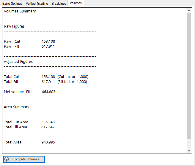
| Volumes Tab |
This tab displays volume
information for the grading surface.
Note: this command requires two Civil Site Design surfaces.
Civil 3D customers have options (noted in the Introduction section) to obtain
volume results. |
| |
|
| Output View |
This screen displays the output volumes.
Users can select text from this screen and copy to other applications |
| Compute Volumes |
Updates the Output View with
volume output data for the current grading design.
Click to update the volume output after making a change to the design |
|
 Open Vertical Grading Window Open Vertical Grading Window |
This opens the Vertical Grading Editor window to enable graphical editing of the string elevations.
Command inputs are as per the  Open Vertical Grading command, with exception to the grid view Open Vertical Grading command, with exception to the grid view
 icon (this will request
the user to refer to the create/edit grading form. icon (this will request
the user to refer to the create/edit grading form.
|
 Open Surface Manager Open Surface Manager |
Click to open the Surface Manager, to set all display options for the ARD Surface created for the Grading String (as well as any other surfaces and model linework). The full details of this form are described in the
 Create/Edit Surface command. Create/Edit Surface command. |