Import from Watercom DRAINS
| Icon: |
|
| Menu: | Pipes > Data Exchange > Import from Watercom Drains |
| Ribbon: | Pipes Tab > Data Exchange Panel > Import from Watercom DRAINS |
Introduction
This command is used to Import information back to CSD Pipes after calculations have been performed in Watercom Drains© for the purposes of creating long sections, cross sections and reports via CSD Pipes.
For the import process to be successful it is required that the user has:
- Exported the CSD Pipes data to Watercom Drains©
- Undertaken a design/analysis in Watercom Drains©
The import must occur on the same project form which the CSD Pipes data was exported.
Special Note: Additional Structures and Pipes created in DRAINS can be included as structures and pipes in Civil Site Design (they are not included automatically in the network - use Create/Update Network to incorporate them into the current network)
Exchange Process with Watercom Drains
Highlighted in Red is the process described in this command.
- Export to DRAINS
- Create the pipe network in Civil Site Design (including Branch Sequencing).
- Add DRAINS Catchments to structures as required
- Establish Structure Bypasses in Civil Site Design and map them to DRAINS Overflows
- Export to Watercom DRAINS - this creates a .xml file suitable
for import into DRAINS
- During export, configure the DRAINS structures and pipes to be created (as required)
- Generate a DRAINS import file (.xml)
- Import to DRAINS
- File > Import > Civil Site Design File... (you must be running an ILSAX model to enable this import function). Select the file created by Civil Site Design.
- Add additional hydraulic features in DRAINS (detention basins, wiers, outlet controls, irregular channels, additional structures and pipes, etc)
- Analyse the storms in DRAINS and redesign pipes and structures as required
- Export from DRAINS
- File > Export > Civil Site Design File... Overwrite the SAME file used for export (you may wish to create a backup copy of the file to reuse if required)
- Import to Civil Site Design
- Import from Watercom DRAINS command
- Select the storm frequency in Civil Site Design to REPLACE with the Drains data (max HGL, flows, etc)
- Open in the Pipe VGE and review - structures and pipes have been edited from Drains. Note: you will not see the HGL from DRAINS shown here.
- Create Long Sections and reports - a prompt will display to use the DRAINS data.
- Export to DRAINS
- Cycle repeats, with the exception that the DRAINS export file will include structure losses, ponding depths and ponding volumes that were calculated or input in DRAINS (unedited by Civil Site Design)
New Structures and Pipes Created in DRAINS
Pipes and structures created in DRAINS can be added to Civil Site Design. This REQUIRES the user to have FIRST exported a pipe network from Civil Site Design to DRAINS using the Export to Watercom DRAINS command.
The x,y coordinates from DRAINS will be used to create the structures. All elevations for the structures and pipes will be adopted from the defined Surface/s in Civil Site Design (the surface data inputted in DRAINS will be lost, possibly with exception of the hydraulic design level).
Users will only be prompted to include structures. Pipes that connect to structures at both ends will also be included automatically.
Overflow routes will not be transferred - users will need to assign a Structure Bypass (which can be used to recreate an Overflow Route for DRAINS).
Note: Structures that do not have pipes connecting to them may not import correctly (and may cause errors). It is strongly recommended that any pipes and structures from DRAINS are connected (each structure services at least 1 pipe, and each pipe is connected to a structure at both ends).
Exchange Settings
The settings as established during the export process (Export to Watercom DRAINS command) are used to establish the mapping of structures from DRAINS to Civil Site Design.
Users can start the Export to Watercom DRAINS process, edit the structure and pipe exchange controls (saving for each) and then Cancel the export. Alternately, if required users can edit the pipe and structure exchange settings via text files using the Edit Conversion Tables command.
Export Items that are a 'Silent' Exchange
The following parameters are not created by Civil Site Design in the export to DRAINS, however if the parameters are found in the DRAINS transfer (.xml) file then they will be carried across into the export file:
- Structure loss factors (ku)
- Sag structure ponding depth
- Sag structure ponding volume
Details
Upon selecting this command, the designer must select the drainage network for import/update from Watercom Drains©. This can be achieved by either selecting the network in the drawing or from a list. Click here for more details on selecting a network.
Following selection of a Drainage network the following form is displayed:
 |
|||||||||||||||||||||||||
| Select CSD Storm Frequency to apply DRAINS results to | Use the pick list to set a storm frequency to apply DRAINS results to. At the time of plotting and reports, the DRAINS results can be used for this storm frequency | ||||||||||||||||||||||||
| OK | Import
the DRAINS data. Pipe and structure data will be adjusted
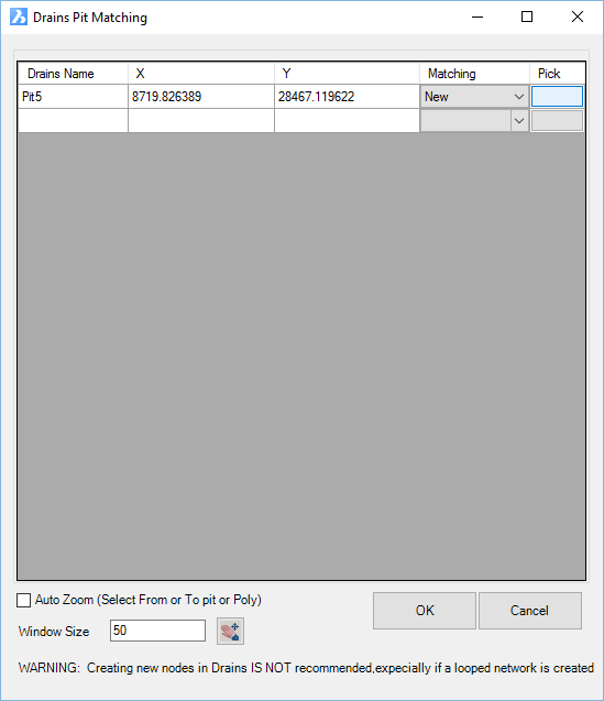
to match DRAINS. Warning messages may display if there were issues with any matching of pipes or structures, or if new pipes or structures were added. If new Structures are detected during import (created in DRAINS and not in Civil Site Design), the software will display the following form for user selection:
|
||||||||||||||||||||||||
