Vertical Grading Editor
| Icon: | |
| Menu: | Pipes > Vertical Grading Editor |
| Ribbon: | Pipes Tab > Edit Panel > Vertical Grading |
Introduction
The Pipes Vertical Grading Editor is one of the central design features of the software and facilitates the vertical grading of your pipe and structure networks.
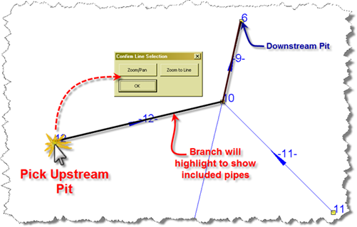
To edit the vertical grading of pipes and structures, users start the command and select an upstream structure - the software traces the branch from the upstream structure to the downstream outlet and presents this in the Vertical Grading Editor window.
Multiple pipe/structure branches can be designed simultaneously for any pipe/structure network and interact dynamically with all other pipe/structure networks, including underground utility obstructions - this enables the designer to see 'real time' the effect of changing the vertical grading of a pipe/structure on all related pipes and structures across multiple networks.
Pre-Requisites
In order to edit pipes and structures the designer must first have created a Network of the pipe and structure collection.
This command is normally preceded by the Create/Edit Network command. In the case of House Connections and Utility Obstructions, a network is created immediately upon creation of these pipe types.
Note: It is recommended also that the Sequence Network command and Apply Object Names commands are executed after creating the network - this allows for branching of the network to be determined as well as the structures and/or pipes to be labelled based on the branch and structure sequencing.
Pipes Vertical Grading Editor - Display
A view of the Vertical Grading Editor is shown, below.
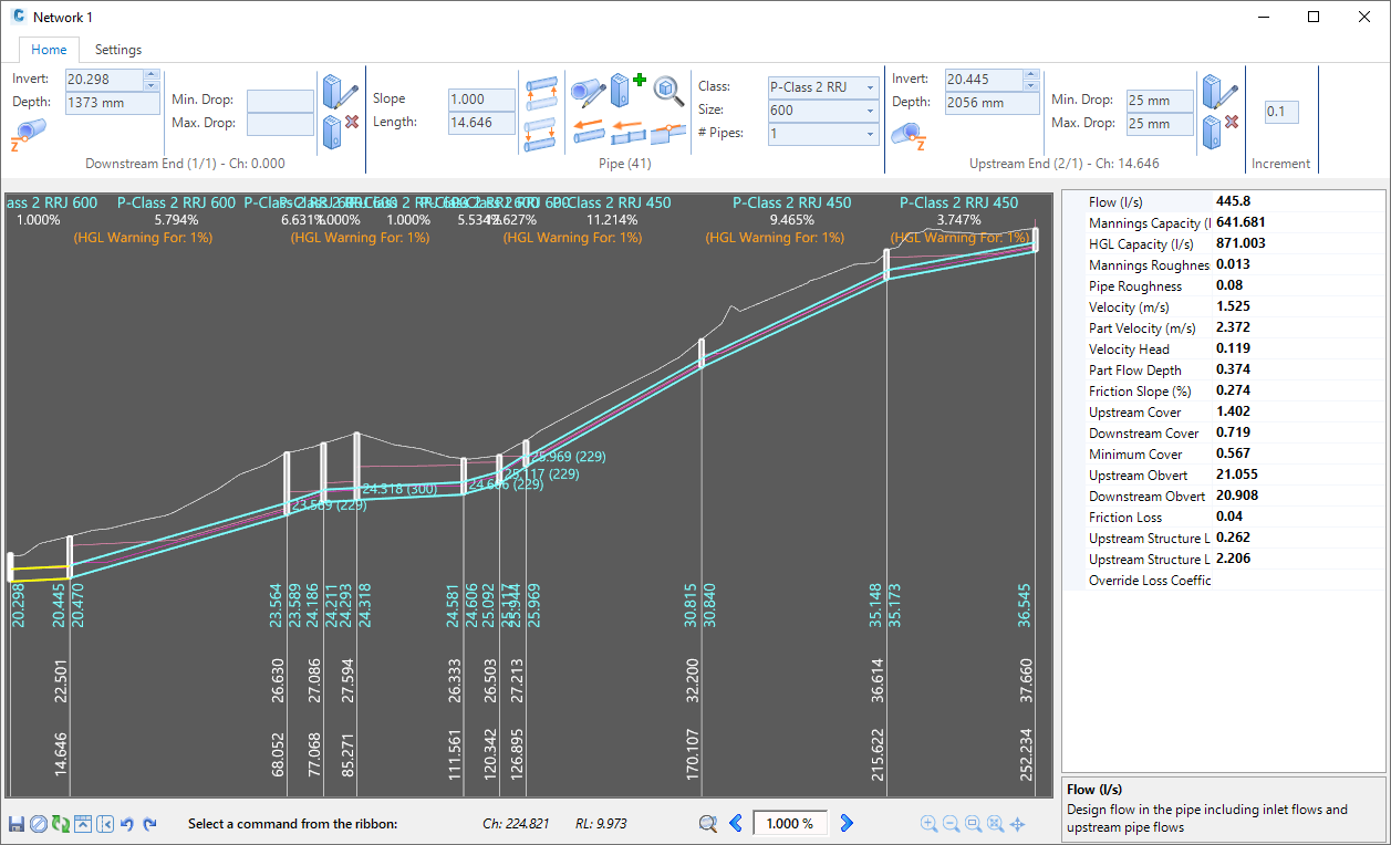
The main components of the Vertical Grading Editor is as follows:
- Ribbon Area (Top)
- Users can start commands from here. The ribbon is split into different panels covering design (Home) and settings.
- Graphical Display Area (Left)
- Displays the pipe design for the branch/es selected, the structures and the incoming pipes at junctions (as textual information of pipe invert and inner diameter). Also displays the surface/s for the network
- At the bottom displays the running distance, surface elevation (design, then existing if design is not present) and the invert elevations
- At the top the display is controllable by the user.
- Text colours and sizes, as well as drawn objects, are controlled in the Settings tab via the Display Settings and Themes.
- Right clicking will highlight a pipe for editing
- Poperties Panel (Right)
- Displays the details for the selected (non editable except for below)
- The Override Loss Coefficient (if shown) is enabled for edit
- Click on
 at the bottom to hide/show this panel
- Information Display Area (Bottom)
 Save VGE
 Close without saving edits
 Refresh Display
 Minimise/Maximise ribbon
- Hide/Show Properties Panel

 Undo/Redo edits
- Describes any command currrently in progress
- Details the exact elevation and distance of the mouse pointer location.
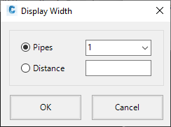
 Zoom to Pipe. Click to automatically set zooming to focus on the highlighted pipe. The folowing form displays. Select the number of pipes to show either side of the current (highlighted) pipe or type a distance to show either side of the current pipe. OK to apply and Cancel to exit:
 use the arrows to select different pipes for editing. This is used to reset the Zoom when the above Zoom to Pipe icon is selected
Note: Using the left and right mouse buttons on the keyboard can also be used for highlighting next/previous pipes for editing.- Includes zoom and pan commands:
 Zoom in
 Zoom out
 Zoom window
 Zoom extents
Note: double clicking the middle mouse will also zoom extents Pan
Pan
About the Vertical Grading Editor
When this command is started, the user is prompted to select a structure graphically off screen or from a list. The Vertical Grading Editor displays structures and pipes from the selected structure to the network outlet.
Pipes are shown from outlet (left) to the selected structure (right). Users select a pipe to edit (highlighted) and then can make changes to the pipe:
- Edit the upstream and/or downstream pipe elevations
- Edit the pipe grade, pipe size/type and number of parallel pipes
- Edit the upstream and/or downstream structures joining the pipe
- Insert in-line structures structures n the network where required
Note: The 'downstream' and 'upstream' structures are more accurately described as the ''structure at start of pipe" and "structure at end of pipe" - users are able to edit the pipe elevations for the pipe fall to change flow direction to be away from the appointed 'downstream structure'.
Select a pipe by:
- right clicking over it
- Using the left/right arrows on the keyboard
- using the

 arrows at the bottom of the window
There are a number of benefits to using the Pipes Vertical Grading Editor. They include:
- Re-scalable Form - change the vertical exaggeration and width of the form simply by dragging at the corner of the window
- Always on Top - the form is always on top, except when an CSD, AutoCAD or Civil 3D command is detected, when it will momentarily minimise
- Dynamic Updating - multiple pipe network branches can be viewed in separate Pipes Vertical Grading Editor windows and crossing pipes are dynamically represented on each VGE window.
- Pipe Grading Tracker - the software includes a 'tracker' in the model space to display the current location when hovering inside a Pipes Vertical Grading Editor window
| The green 'tracker' symbol traces along the pipe to show the designer the current location in the model whilst vertically grading the pipe network branch. |
Vertical Design - Automatic and Manual
When the pipe Vertical Grading is first displayed, elevations are assigned based on a number of rules:
- Pipe minimum slope controls
- Pipe minimum cover controls
- Drop requirements across structures
The pipe size is also assigned to carry the design flows in each pipe.
The user is able to change the pipe type and size, the downstream elevation and upstream elevation of the pipe. When a pipe edit is made, the user is alerted to the change with the addition of a ![]() 'user set' icon displaying next to the control that has been user edited (downstream elevation, upstream elevation or pipe type/size).
'user set' icon displaying next to the control that has been user edited (downstream elevation, upstream elevation or pipe type/size).
If the ![]() symbol is displayed, then that input has been set by the user. Clicking on the
symbol is displayed, then that input has been set by the user. Clicking on the ![]() icon will restore back to the 'automatic' user design.
icon will restore back to the 'automatic' user design.
Starting the Vertical Grading Editor
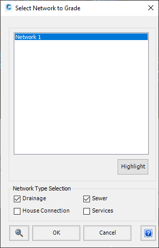
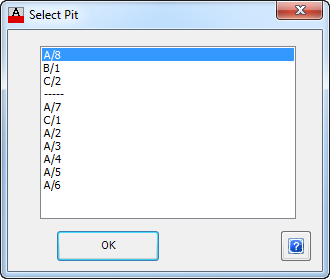
Upon selecting this command, at the Command prompt the user will be asked to "Select Structure on a Network or Press <Enter> to Select from a Network and then a Structure Number".
There are two methods for selecting a part of the network to edit in the Vertical Grading Editor.
Users can either:
Common Issues When Selecting a Structure
The following issues and prompts can result when selecting a structure for presentation of a pipe branch in the editor:
|
Error Message |
Cause |
||||
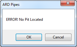 |
The mouse selection point is too far from the location of a structure in the drawing - the software has not detected any structure within the required distance from the selected point. Form details are as follows:
|
||||
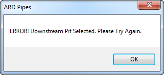 |
The designer has selected the most downstream structure in a network. As the software is tracing structures working from the upstream structure to the downstream structure, it is unable to located pipes/structures to present in the Pipes Vertical Grading Editor window. Form details are as follows:
|
Details |
|

Upon opening the Vertical Grading Editor the following form is displayed:
|
Home Tab |
Includes controls for editing of the selected pipe |
|||||||||||||||||||||||||||||||||||||||||||||||||||
|
Downstream End (Name) - Ch: XXX.XXX |
Displays details regarding the downstream pipe and downstream structure. The name assigned to the structure is contained in the brackets. Ch: XXX.XXX shows the distance of the pipe end, measured from the outlet |
|||||||||||||||||||||||||||||||||||||||||||||||||||
| Invert |
Displays the current pipe invert elevation. Use the up/down arrow toggles to raise/lower the pipe by the specified Increment (input control on this display). | |||||||||||||||||||||||||||||||||||||||||||||||||||
| Depth | Non editable field. Displays the depth to invert for the pipe, taken as the distance from the pipe invert to the nominated Design surface and measured at the structure centreline. | |||||||||||||||||||||||||||||||||||||||||||||||||||
|
|
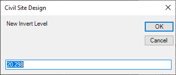
Click to type in an invert elevation.
|
|||||||||||||||||||||||||||||||||||||||||||||||||||
| |
This symbol displays whenever a user change is applied to the downstream elevation, to identify that the automatic design is no longer being applied. Click on this icon to revert back to the software automated design. |
|||||||||||||||||||||||||||||||||||||||||||||||||||
| Min Drop | This displays the minimum drop (mm) of all pipes connected to this structure. | |||||||||||||||||||||||||||||||||||||||||||||||||||
|
Max Drop |
This displays the maximum drop (mm) of all pipes connected to this structure. |
|||||||||||||||||||||||||||||||||||||||||||||||||||
| |
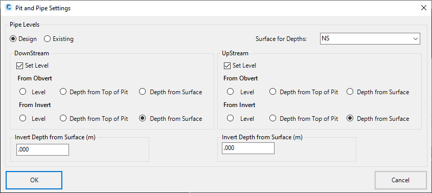
Click to edit the structure properties including structure top level, structure bottom level and pipe level constraints.
A form will display to eidt the structure properties. The form display and inputs are as as described in the Edit Structure Properties command EXCEPT that the structure plan location control is disabled. Click OK or Cancel to return to the Vertical Grading Editor. |
|||||||||||||||||||||||||||||||||||||||||||||||||||
| |
Click on this icon to delete the downstream structure of the highlighted pipe. A confirmation message will display - click OK to confirm deletion of the structure. Note: users will not be permitted to delete a structure at a junction, the downstream structure or structure immediately preceding the downstream structure. Error messages will display for these occurrences and the structure will not be deleted. Click OK to exit the forms. |
|||||||||||||||||||||||||||||||||||||||||||||||||||
| Pipe (Name) | Enables editing of the pipe. The name assigned to the pipe is contained in the brackets. | |||||||||||||||||||||||||||||||||||||||||||||||||||
| Slope (%) or Slope 1: | This displays the pipe grade (%) or pipe slope (1:) and is a non-editable field. Note: The method of slope input is controlled via the Active Network Settings form. Users can select the slope input method pending the network type. |
|||||||||||||||||||||||||||||||||||||||||||||||||||
| Length | This displays the pipe length and is a non-editable field. | |||||||||||||||||||||||||||||||||||||||||||||||||||
| |
Move the entire pipe up by the Increment value. Note: if the pipe elevation at either end has been set as a depth to the top of structure or a depth to surface the user will be prompted to override this control |
|||||||||||||||||||||||||||||||||||||||||||||||||||
| |
Move the entire pipe down by the Increment value. . Note: if the pipe elevation at either end has been set as a depth to the top of structure or a depth to surface the user will be prompted to override this control |
|||||||||||||||||||||||||||||||||||||||||||||||||||
| |
Excepting extra controls in the Edit Pipe Properties command to edit the Pipe Class, Pipe Item and Number of Pipes, this form matches the functionality as described in the Edit Pipe Properties command. Click on the image or click here to view the details of this command. |
|||||||||||||||||||||||||||||||||||||||||||||||||||
| |
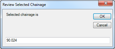
Click on this icon to insert a new structure in line with the currently highlighted pipe. Upon selecting this icon the command prompt in the Vertical Grading Editor Reporting Panel will prompt 'Select Structure Insert Position'. Use the mouse to graphically position a location for the structure and click the left mouse button to make the selection. Note: Selecting a location in the Vertical Grading Editor window that is not within the chainage range of the currently highlighted pipe will result in an error message being displayed and the structure will not be inserted. Click OK to exit the message and restart the command. Upon selecting a valid location for the structure the following form will display.
Review the assigned structure family and structure type applied. The assigned Structure Family and Structure Type is controlled from the Active Network Settings. |
|||||||||||||||||||||||||||||||||||||||||||||||||||
| |
Click to zoom to the selected pipe in the drawing. | |||||||||||||||||||||||||||||||||||||||||||||||||||
| |
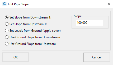
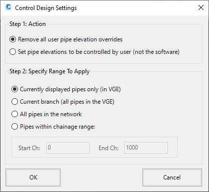
Click on this icon to open the following form:
|
|||||||||||||||||||||||||||||||||||||||||||||||||||
| |
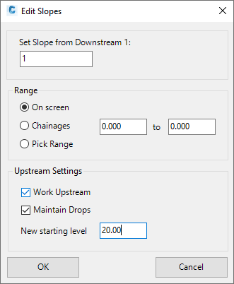
Click on this icon to open the following form:
|
|||||||||||||||||||||||||||||||||||||||||||||||||||
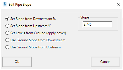
| |
Click on this icon to edit the upstream or downstream end of a pipe to match the obvert level of the next upstream or downstream pipe at the structure. This command works on any pipe displayed in the Vertical Grading Editor window, except for the upstream end of the most upstream pipe or the downstream end of the most downstream pipe shown in the Vertical Grading Editor. Upon selecting this command prompt in the Vertical Grading Editor Reporting Panel will prompt 'Select pipe obvert to change)'. Use the mouse to graphically and click the left mouse button to select one end of a pipe that is located close to a structure to change and set the obvert level of that end of the pipe. The obvert level will be adjusted to match the obvert level of the next downstream (if the downstream end of the pipe was selected) or upstream (if the upstream end of the pipe was selected) pipe located at the structure. Upon completion of the command the end of the pipe will have it's obvert elevation set to match. This will set the pipe elevation for the end of the pipe that is selected. Note: If the next upstream or downstream pipe does not have its elevation at the structure set then the upstream or downstream pipe may be further adjusted after the obverts are matched to maintain either the cover, structure drop, minimum grade, capacity or velocity controls. If the next upstream or downstream pipe is adjusting so the obverts do not match you will need to set the elevations of this end of the pipe. |
|||||||||||||||||||||||||||||||||||||||||||||||||||
| Class | This displays the Pipe Class. Use the pick list to select the required Pipe Class. | |||||||||||||||||||||||||||||||||||||||||||||||||||
| Diameter | This displays the Pipe Identifier. Use the pick list to select the required Pipe Identifier. | |||||||||||||||||||||||||||||||||||||||||||||||||||
| # Pipes | This displays the number of parallel pipes being applied. This cell cannot be edited in the Vertical Grading Editor. To increase the number of parallel pipes being applied, exit the Vertical Grading Editor and start the Edit Pipe Properties command. | |||||||||||||||||||||||||||||||||||||||||||||||||||
| |
This symbol displays whenever a user change is applied to the pipe type, size or number of pipes, to identify that the automatic design is no longer being applied. Click on this icon to revert back to the software automated design. Note: If the downstream or upstream pipe elevations are user edited (not automatic) then the pipe class/size/number will not revert back to the 'automatic' values. |
|||||||||||||||||||||||||||||||||||||||||||||||||||
|
Upstream End (Name) - Ch: XXX.XXX |
Displays details regarding the downstream pipe and downstream structure. The name assigned to the structure is contained in the brackets. Ch: XXX.XXX shows the distance of the pipe end, measured from the outlet |
|||||||||||||||||||||||||||||||||||||||||||||||||||
| Invert |
Displays the current pipe invert elevation. Use the up/down arrow toggles to raise/lower the pipe by the specified Increment (input control on this display). | |||||||||||||||||||||||||||||||||||||||||||||||||||
| Depth | Non editable field. Displays the depth to invert for the pipe, taken as the distance from the pipe invert to the nominated Design surface and measured at the structure centreline. | |||||||||||||||||||||||||||||||||||||||||||||||||||
|
|
Click to type in an invert elevation.
|
|||||||||||||||||||||||||||||||||||||||||||||||||||
| |
This symbol displays whenever a user change is applied to the downstream elevation, to identify that the automatic design is no longer being applied. Click on this icon to revert back to the software automated design. |
|||||||||||||||||||||||||||||||||||||||||||||||||||
| Min Drop | This displays the minimum drop (mm) of all pipes connected to this structure. | |||||||||||||||||||||||||||||||||||||||||||||||||||
|
Max Drop |
This displays the maximum drop (mm) of all pipes connected to this structure. |
|||||||||||||||||||||||||||||||||||||||||||||||||||
| |
Click to edit the structure properties including structure top level, structure bottom level and pipe level constraints.
A form will display to eidt the structure properties. The form display and inputs are as as described in the Edit Structure Properties command EXCEPT that the structure plan location control is disabled. Click OK or Cancel to return to the Vertical Grading Editor. |
|||||||||||||||||||||||||||||||||||||||||||||||||||
| |
Click on this icon to delete the downstream structure of the highlighted pipe. A confirmation message will display - click OK to confirm deletion of the structure. Note: users will not be permitted to delete a structure at a junction, the downstream structure or structure immediately preceding the downstream structure. Error messages will display for these occurrences and the structure will not be deleted. Click OK to exit the forms. |
|||||||||||||||||||||||||||||||||||||||||||||||||||
| Increment | The amount that the pipe start will raise/lower upon selection of the raise/lower controls. Type in the increment raise/lower value. The following controls use this value:
|
|||||||||||||||||||||||||||||||||||||||||||||||||||
|
Settings Tab |
Includes controls for managing the display in the Vertical Grading Editor window. |
|||||||||||||||||||||||||||||||||||||||||||||||||||
|
Display Panel |
Manages the display of information | |||||||||||||||||||||||||||||||||||||||||||||||||||
| Exaggeration |
Picklist to select the desired maximum vertical exaggeration. |
|||||||||||||||||||||||||||||||||||||||||||||||||||
| Current Exaggeration | Displays the actual exaggeration applied. The software sets this by reviewing the network extents and ascertaining what can be displayed. If Zoom to Pipe is selected, then it changes to include the pipes set to display (when the next/previous pipe icons are selected to toggle the current pipe). | |||||||||||||||||||||||||||||||||||||||||||||||||||
| Show Properties Window | Turns on/off the display of the Properties Panel - this panel expands to the right of the windwo and contains the selected pipe properties. | |||||||||||||||||||||||||||||||||||||||||||||||||||
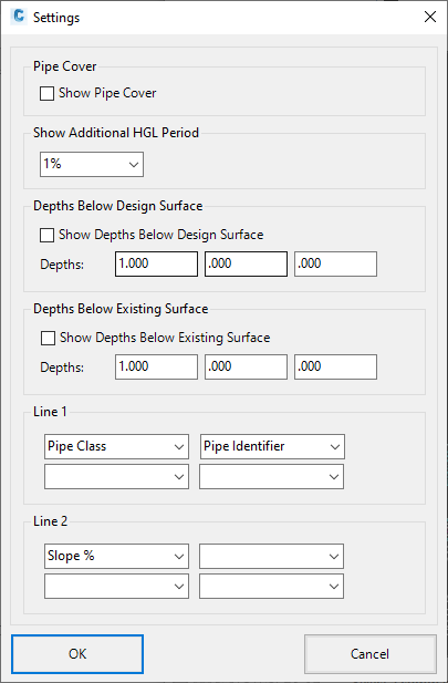
| Show Pipe Cover | Draws a line above each pipe to show the cover requirements above the pipe. | |||||||||||||||||||||||||||||||||||||||||||||||||||
| Show HGL Warning | For every storm likelihood selected, the software will do a Hydraulic Grade Line (HGL) calculation. If the HGL is above the Freeboard for a particular storm likelihood, it can be identified in the display with the warning message 'HGL Warning for: XX', where XX is the storm likelihood. Toggle to turn this text display on/off. |
|||||||||||||||||||||||||||||||||||||||||||||||||||
| Show Depths below Design | A copy of the design surface can be drawn a set distance below the current. Type in the distance to display and use the tick box to show/hide | |||||||||||||||||||||||||||||||||||||||||||||||||||
| Show Depths below existing | A copy of the existing surface can be drawn a set distance below the current. Type in the distance to display and use the tick box to show/hide | |||||||||||||||||||||||||||||||||||||||||||||||||||
| |
The following form is displayed and inputs are as follows:
|
|||||||||||||||||||||||||||||||||||||||||||||||||||
| |
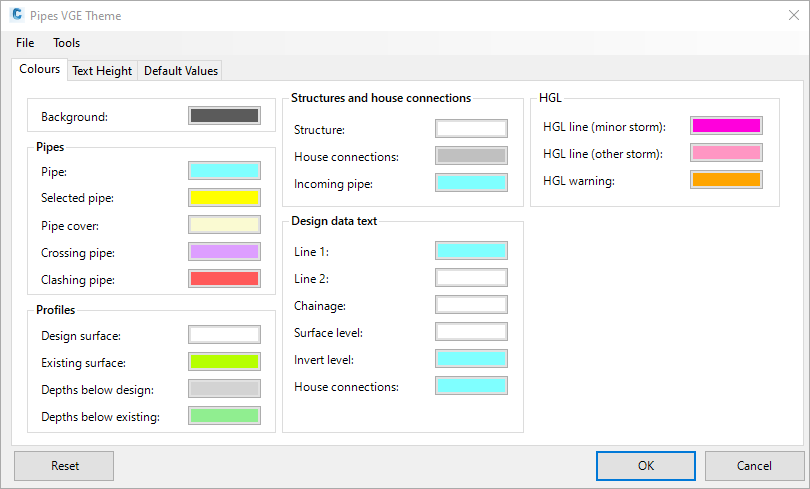
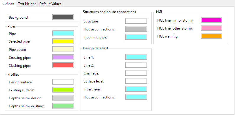
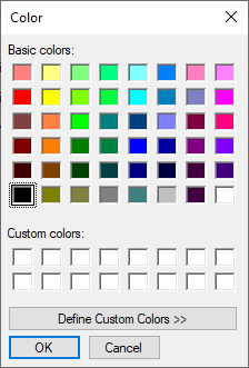
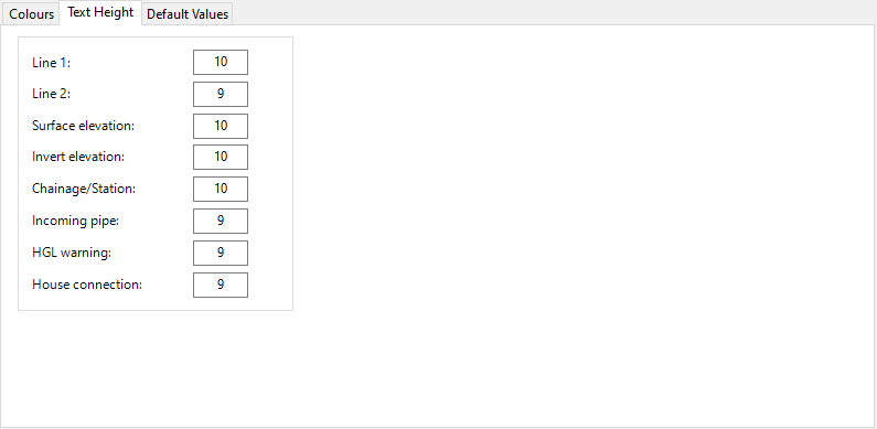
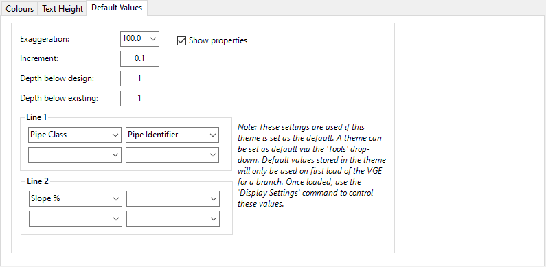
The Theme form allows users to set the colours, scales, and display of information. Inputs as follows:
|
|||||||||||||||||||||||||||||||||||||||||||||||||||
| |
The following form is displayed and inputs are as follows:
|
|||||||||||||||||||||||||||||||||||||||||||||||||||
|
|
Information Display Area (Bottom) | |||||||||||||||||||||||||||||||||||||||||||||||||||
|
Save the current design status of pipes in the Vertical Grading Editor |
||||||||||||||||||||||||||||||||||||||||||||||||||||
| Exit the vertical grading editor and roll back edits made in that window | ||||||||||||||||||||||||||||||||||||||||||||||||||||
| Redraws the pipes and dispaly | ||||||||||||||||||||||||||||||||||||||||||||||||||||
|
|
Click to maximis or minimise the ribbon tab at the top | |||||||||||||||||||||||||||||||||||||||||||||||||||
|
|
The properties panel, displaying pipe information, located on the right of the graphics area, can be turned on/off with this button | |||||||||||||||||||||||||||||||||||||||||||||||||||
| Undo/Redo pipe elevation/size changes made in the Vertical Grading Editor window | ||||||||||||||||||||||||||||||||||||||||||||||||||||
| Command prompt | Displays the expected action when a command is started | |||||||||||||||||||||||||||||||||||||||||||||||||||
| Coordinate tracker | Displays the distance and elevation of the mouse position | |||||||||||||||||||||||||||||||||||||||||||||||||||
Click to automatically set zooming to focus on the highlighted pipe when using the
|
||||||||||||||||||||||||||||||||||||||||||||||||||||
| Toggles to highlight the previous pipe for edit Note: pressing the left arrow on the keyboard will apply this command |
||||||||||||||||||||||||||||||||||||||||||||||||||||
| Pipe Slope | Displays the % pipe slope | |||||||||||||||||||||||||||||||||||||||||||||||||||
| Toggles to highlight the next pipe for edit Note: pressing the right arrow on the keyboard will apply this command |
||||||||||||||||||||||||||||||||||||||||||||||||||||
| Zooms in by 25% | ||||||||||||||||||||||||||||||||||||||||||||||||||||
| Zooms out by 25% | ||||||||||||||||||||||||||||||||||||||||||||||||||||
| Click twice to select a window to zoom to | ||||||||||||||||||||||||||||||||||||||||||||||||||||
|
|
Zooms to the extents of the pipes selected for display Note: double clicking the middle mouse will also zoom extents |
|||||||||||||||||||||||||||||||||||||||||||||||||||
| Click two spots to apply a pan action | ||||||||||||||||||||||||||||||||||||||||||||||||||||
 or
or