Viewer Settings
Icon:
![]()
Ribbon: Model Viewer > Home Tab > Settings Panel > Viewer Settings
Introduction
Settings for Model Viewer can be managed by the user via the Viewer Settings command. These settings include customisation of the Model Viewer interface and assignment of default styles for when Model Viewer is first used on a project.
Information on navigation in the Model Viewer 3D environment is available when reviewing the Model Viewer command help.
Details
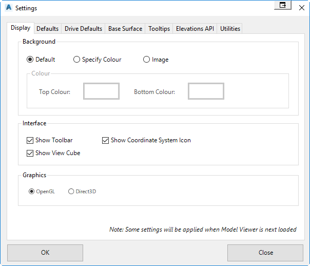
Upon selecting the command the following form is displayed:
Display Tab
|
|
|
|
Background |
Users can customise the Model Viewer background by defining colours or an image from file. |
| Default | Sets the Model Viewer background to utilise the default style |
| Specify Colour | Allows the user to specify a top colour and a bottom colour to create a gradient for the background |
| Image | Users can specify an image loaded from file for the background. |
|
Interface |
Allows user to toggle on/off some of the display tools in Model Viewer |
| Show Toolbar | Users can toggle on/off the Model Viewer toolbar. This toolbar includes commands to zoom and pan around the model. |
| Show View Cube | Users can toggle on/off the Model Viewer view cube. The view cube is a handy tool allowing the user to quickly navigate to different views in the model |
| Show Coordinate Icon | Users can toggle on/off the Model Viewer coordinate icon. The coordinate icon is shown at the bottom-right corner of Model Viewer and displays the x,y, and z axis. |
|
Graphics |
|
| OpenGL | Use OpenGL graphics renderer to display |
| Direct 3D | Use Direct3D (Microsoft) graphics renderer to display |
|
OK |
Apply and exit. |
|
Cancel |
Exit the form |
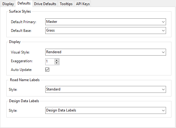
Defaults Tab
|
|
|
|
Surface Styles |
When a Model Viewer is first used on a project, the Toggle Display form will show. The default styles set in this form can be specified by the user here. |
| Default Primary | Allows the user to specify the default style for the Primary Surface. All available design styles are listed here. |
| Default Base | Allows the user to specify the default style for the Base Surface. All material groups are listed here. |
|
Display |
Allows user to customise the default display options for when Model Viewer is first displayed. |
| Visual Style | Users can specify the default visual style. |
| Exaggeration | Users can specify the default exaggeration value. |
| Auto Update | Users can toggle on/off the auto update option. |
|
Road Name Labels |
Specify whether labels showing the road names will appear in Model Viewer on first load |
| Style | Specify the default label style for road name labels. |
|
Design Data Labels |
Specify whether labels showing the design data for main road will appear in Model Viewer on first load |
| Style | Specify the default label style for design data labels. |
|
OK |
Apply and exit. |
|
Cancel |
Exit the form |
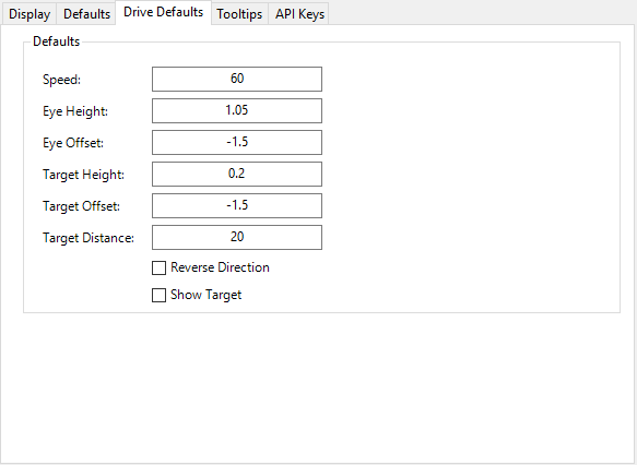
Drive Defaults Tab
|
|
|
|
Defaults |
|
| Speed | Sets the default speed value when the Drive command is used |
| Eye Height | Sets the default eye height value when the Drive command is used |
| Eye Offset | Sets the default eye offset value when the Drive command is used |
| Target Height | Sets the default target height value when the Drive command is used |
| Target Offset | Sets the default target offset value when the Drive command is used |
| Target Distance | Sets the default target distance value when the Drive command is used |
| Reverse Direction | Sets whether the Drive command will default to driving from the reverse end of the alignment |
| Show Target | Sets whether a yellow sphere is displayed at the target height and target offset when the Drive command is used |
|
OK |
Apply and exit. |
|
Cancel |
Exit the form |
Tooltips Tab
|
|
|
|
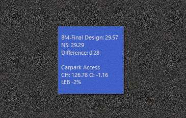
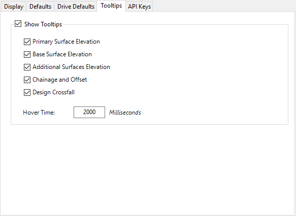
Show Tooltips |
Toggle on/off the display of tooltips in Model Viewer. All very large projects with plenty of road objects, users can increase performance of the tooltip by toggling off some of the items listed below. |
| Primary Surface Elevation | Toggle on/off the display of the primary surface elevation set in the toggle display command. |
| Base Surface Elevation | Toggle on/off the display of the base surface elevation set in the toggle display command. |
| Additional Surfaces Elevation | Toggle on/off the display of elevations for additional surfaces set in the toggle display command. |
| Chainage and Offset | Toggles on/off the display of chainage & offset information for the nearest road object. |
| Design Crossfall | Toggles on/off the display of code crossfall information for the nearest road object. |
| Hover Time | Sets the hover time of the mouse before the tooltip is displayed. |
|
OK |
Apply and exit. |
|
Cancel |
Exit the form |
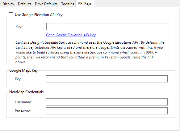
API Keys Tab
|
|
|
|
Use Google Elevation API Key |
The satellite from surface command uses the Google Elevations API to attain elevation data. By default, there is a limit of 10,000 points per surface when using this command. However, by specifying your own Google Elevations API key, you can turn off this point limit. A Google Elevations API key can be attained here. |
| Key | Specify your Google Elevations API Key to turn off the point limit of 10,000 points per surface. |
|
Google Maps Key |
If you have a Google Maps Key, then you can specify it for when accessing aerial imagery in Model Viewer. This is required for users who exceed for than 25,000 map loads per 24 hours. |
| Key | Specify your Google Maps API Key. |
|
NearMap Credentials |
When importing aerial imagery into Model Viewer, users have the option to reference NearMap data if they have a valid account. In order to reference NearMap data, it will be required to specify your username and password information. |
| Username | Specify your NearMap account username. |
| Password | Specify your NearMap account password. |
|
OK |
Apply and exit. |
|
Cancel |
Exit the form |