Satellite From Surface
Icon: ![]()
Introduction
The Surface From Satellite command allows users to generate a
Civil Site Design Surface by referencing online elevation data.
This command can be accessed directly from the Roads tab on the
ribbon or via the Toggle
Display dialog in Model Viewer.
The elevation data used to build this surface is attained using the
Google
Elevations API. Building a surface from this data is great for
conceptual design or for the purpose of extending an existing Civil
Site Design Surface. Currently, we have capped the point limit for
a single surface at 10,000. However, you can set this limit to be unlimited
if you attain a Google
Elevations API Key and specify this in the Viewer
Settings.
Image Display
The image is automatically download and inserted in the drawing. The image is moved, scaled and rotated to align with the inserted surface.
Image Quality Notification
By default, the highest quality imagery will be downloaded. If the software detects that this process may take some time, a message will display to advise that the time may extend into minutes and an option will be provided to donwload lower quality image tiles instead.
Details
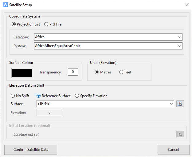
Upon selecting the command the following form is displayed:
|
|
| Coordinate System | Select the coordinate system to use for importing your data to the drawing |
| Projection List (Recommended) | Prior to importing surface data, it is required that the user specify the coordinate system. Users have the option of either selecting one of the known built-in coordinate systems (via the Projection List) or specify a projection file. Projection files can be attained via the Spatial Reference website and should be used only if the coordinate system cannot be found in the projection list. If using the Projection List option, users will be required to first specify the category of the system and after doing so will populate a list of known coordinates systems. The Projection List is the recommended method for specifying the coordinate system, because it also contains details on how to transform coordinates systems from one to another. |
| Category | Select the coordinate system category. For example, specify 'NationalGridsAustralia' to view known coordinates systems for Australia. |
| System | After selecting a category, all available coordinates systems will be listed in this drop-down box. |
PRJ File |
Prior to importing surface data, it is required that the user specify the coordinate system. Users have the option of either selecting one of the known built-in coordinate systems (via the Projection List) or specify a projection file. Projection files can be attained via the Spatial Reference website. On selecting the button with the 3 dots, the software will open the Model Viewer Projections Folder. If your coordinate system is not listed, then select the link to access the Spatial Reference website to search and download the .prj file for your required coordinate system. |
Surface Colour |
Specify the colour of the Civil Site Design Surface |
| Colour Select | Specify the colour of the Civil Site Design Surface. This colour will be used when Model Viewer is display with a Shaded Visual Style. |
| Transparency | Type in a surface transparency (0-100) |
Units (Elevation) |
|
| Metres/Feet toggle | Pick whether the elevations
downloaded are in metres or feet. The default value for this will be
set by the units specified in the Active Drawing Settings
form. Note: This setting does not affect the X,Y coordinates of the points. |
Elevation Datum Shift |
Allows the user to shift the elevations of the downloaded data |
No Shift |
The downloaded elevations are not shifted |
Reference Surface |
This option allows the user to shift the elevations by referencing an existing Civil Site Design Surface. The user is required to specify a surface and a coordinate (by selecting the picker button). The elevation taken from the existing surface is used to shift the elevations of the downloaded data. By using a Reference Surface, the software will also know where you are in the world and therefore when the satellite imagery will default to this location. |
| Specify Elevation | This option allows the user to specify either a negative or positive value to shift the downloaded elevations on to the correct datum. |
Surface |
If Reference Surface is specified, then the user will be required to select this surface from the list. |
Elevation |
If Elevation is specified, then the user is required to specify the negative or positive value for the elevation shift. |
|
Initial Location (Optional) |
A position can be selected in the drawing and used to set a starting position to view in the Satellite Imagery form. |
| Pick Location | Click on the icon to then select a location in the drawing. Upon selection of a position in the drawing this form will redisplay and the selected coordinates display (x,y) |
| Confirm Satellite Data | The Surface from Satellite window is displayed allowing users to define the area to generate the Civil Site Design Surface. |
| Cancel | Exit the command without building a new Civil Site Design Surface. |
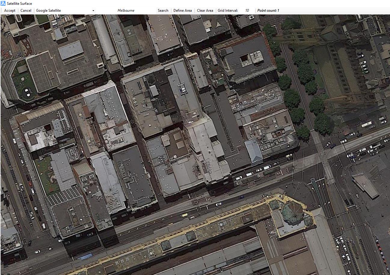
Upon selecting the Confirm Satellite Data button, the following window is displayed. This window allows the user to specify the area to generate the Civil Site Design Surface.
|
|
| Map Provider | Specify the map provider you would like to reference. Options include Bing Maps, Google Maps, and NearMaps - NearMaps can only be used once credentials are specified in the Viewer Settings. |
| Search Field | The first step is to search for the area. In the search field (defaulting to the text 'Melbourne'), type in the address and select the ENTER key. If found, the software will pan to the location. By holding down the right-mouse button, users can pan around the view. |
| Note: If 'Pick Location' was set, a pin will display for the position selected in the drawing | |
Define Area |
Once zoomed to the location of choice, use the Define Area button to specify the area. Upon selecting the button, the user is first required to select the top-left corner of the area. On doing so, the software will shift the view to this location. Next, the user is required to select the bottom-right corner. Upon doing so, a red area is highlighted indicating the area to be downloaded. |
Clear Area |
This option allows the user to clear the currently defined area allowing the user to define a new area. |
| Grid Interval | This value is the intensity of the points downloaded. As this value is edited, the Point Count value will changed so the user is aware of how any points will be downloaded. By default, the download limit for a given surface is 10,000. However. users can make this value unlimited by using their own Google Elevations API Key, which is the defined in the Viewer Settings. |
| Accept | The software will download the elevations for the area specified. |
| Cancel | Exit the command without building a new Civil Site Design Surface. |
Once the elevations have been downloaded, the Civil Site Design Create Surface form will display. The user then specifies whether to create a new Civil Site Design Surface or update an existing Civil Site Design Surface. If creating a new surface, the user will be required to specify the name of the new surface and the surface style.