Toggle Display
Icon:
![]()
Ribbon: Model Viewer > Home Tab > View Panel > Toggle Display
Introduction
The Toggle Display command allows users to manage the display of surfaces, point clouds, system labels, lighting and other settings in Model Viewer. The Toggle Display dialog will load when you first run the Model Viewer command on a project. The default styles assigned to the Primary Surface, Base Surface, and system labels can be setup in the Viewer Settings.
This command is very much associated with the Refresh command, because the Refresh command will update the display of data as setup in the Toggle Display dialog. If there are issues with the display of information in Model Viewer, than it recommend that you first review the Toggle Display setup.
In Model Viewer, users can specify a Primary Design Surface and a Base Surface. The Primary Surface is the main design surface and commands such as Assign Materials to Triangle will reference only the Primary Surface.
About the Primary Design Surface
The Primary Design Surface is best set as the main design surface (eg: AutoModel). Because design surfaces have coded breaklines, materials can be assigned between the coded triangle edges.
For surveyed surfaces, setting the surveyed surface as the Primary Design will enable materials to be assigned based on the coded survey points.
About the Primary Design Surface
The Base Surface is generally set as your existing terrain surface. Users have the ability to drape aerial imagery over the Base Surface and parts of the Base Surface can be trimmed out where design surfaces exist. The Trim Base (surface) is used when it required to trim the Base Surface out using the extents of the specified design surface.
Notes:
-
Clicking OK on this form will force a refresh of Model Viewer.
-
Information on navigation in the Model Viewer 3D environment is available when reviewing the Model Viewer command help.
Details
Upon selecting the command the following form is displayed:
File Menu
| Save Display | Users have the option to save parameters set in the Toggle Display form. The is useful for users who have a long list of surface models and want to save and reload different display states. |
| Open Display | Users have the option to open saved parameters in the 'Toggle Display' form. The is useful for users who have a long list of surface models and want to save and reload different display states. It is recommended that if the Combined Surface command is used, then the user should save this display so that the display can be re-loaded if an update to the combined surface is required. |
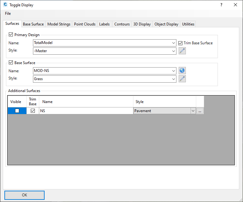
Surfaces Tab
|
|
|
|
Primary Design |
Set as the main design surface displayed in Model Viewer. The display of this surface can be toggled on/off. Commands such as Assign Materials to Triangle will only reference this surface. |
|
Name |
All design surfaces are listed here. Only surfaces created using commands such as Auto Model, Model Builder, Grading will be listed. The Trim Base (surface) is used when it required to trim the Base Surface out using the extents of the specified design surface. |
| Style |
All design surface styles are listed. Users can create/edit
a design style
if required, by selecting
|
|
Base Surface |
The Base Surface is generally set as your existing terrain surface. Users have the ability to drape aerial imagery over the Base Surface and parts of the Base Surface can be trimmed out where design surfaces exist. The Trim Base (surface) is used when it required to trim the Base Surface out using the extents of the specified design surface. The display of this surface can be toggled on/off. |
| Name | All non-design surfaces are listed here. These are surfaces such as AutoCAD Civil3D surfaces or surfaces created using Civil Site Design's Create/Edit Surface command. |
| Style | Users have the option to either drape an aerial image over this surface or assign a material group. If the user selects Image from Drawing (Aerial Photo), a dialog will display with an option to select an image from the drawing. Model Viewer will reference the image directly from its file path. The position and scale of the image will reflect the position and scale of the image in the drawing. |
|
Additional Surfaces |
All other surfaces in the project are listed here. Users have the option to toggle on/off the visibility of these surfaces and set whether they will trim out the Base Surface. These surfaces can be styled by assigning a material group. Selecting the button '...' will open the material groups dialog. |
|
OK |
Apply and exit. |
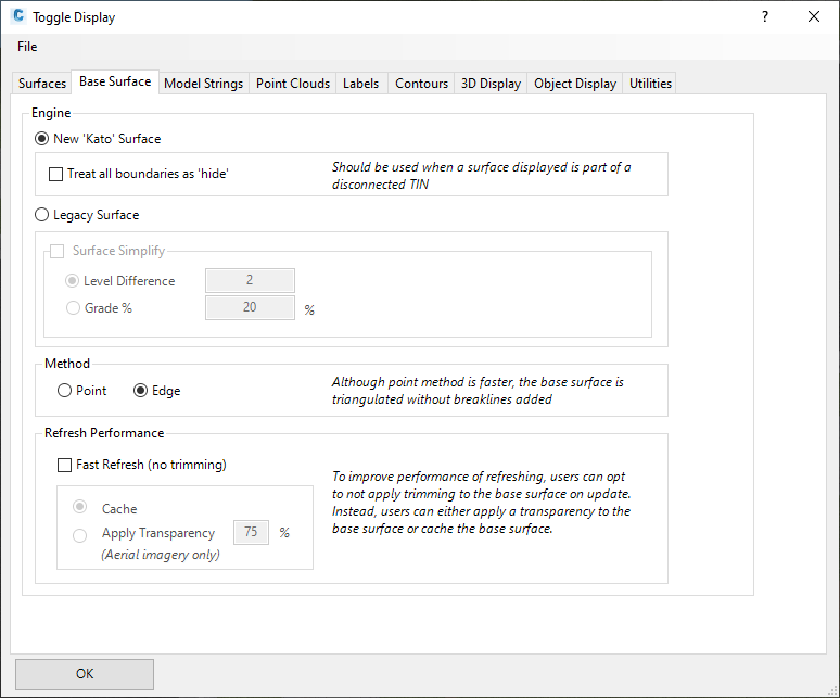
Base Surface Tab
|
|
|
| Engine | Users have options as to how the surface is built and updates |
| New 'Kato' Surface toggle option |
Default computational engine. This method of surface
creation is superior to th Legacy Surface method (the only
method in use up until Civil Site Design V19.20 release): - Much faster creation and display than the Legacy Surface method - Better performance on large surfaces - Full boundary support on the base surface - The base surface has more comprehensive boundary options (hiding the base surface whenever another surface is set to 'trim' the base) including support for multiple boundary surfaces |
| Treat all Boundaries as Hide |
Tick this on if the Design Surface, or an Additional
Surface, is set to Trim the base and has multiple boundaries
(resulting in it being discontinuous - simulating having two
outer boundaries applied). Note: If ticked on, every Hide boundary of every 'trimmed' surface will be included. This may require users to either create a surface to trim to in the hide boundary areas, or use the Paste Surface command to create a single connected TIN Surface of these. |
| Legacy Surface Toggle Option | Tick this on to use the pre V19.20 release surface computational engine. |
|
Surface Simplify |
Toggle on/off surface simplification (legacy surface method only). Can improve performance and address problems with trim boundaries. |
| Level Difference | Triangles are removed from the Base Surface using a level difference method. |
| Grade | Triangles are removed from the Base Surface using a grade difference method. |
|
Method |
|
| Point | Using this method, the Base Surface is formed by re-triangulating the points that make up the surface specified. This method is faster, however less accurate as the edges of the surface specified are not always honoured. |
| Edge | Using this method, the Base Surface is created using the edges of the surface specified. This Base Surface formed is an accurate representation of the surface specified. |
|
Refresh Performance |
|
| Fast Refresh | The slowest part of running a refresh in Model Viewer is the re-calculation of the base surface when it is required to trim the triangulation. Users have the option to toggle off the trimming of the base surface to considerably increase the performance of Model Viewer refreshing. This option is recommended when working with really large terrain data or if only minor changes are expected to be made to the the surface models on refresh. |
| Cache | When the software first calculates the base surface (inclusive of trimming), the software will record this information to memory. So on each refresh to the model. the cached base surface is used rather than a re-calculated base surface. This is recommended when working with large detailed surface data or when the job is almost complete and the user is simply working in Model Viewer to perform sight distance checks, import 3d models, or when it is not required to completely re-calculate the base surface. |
| Apply Transparency | This option will turn off trimming of the base surface completely. The base surface will then be displayed with a transparency, so the user can still see design data that exists below the base surface. |
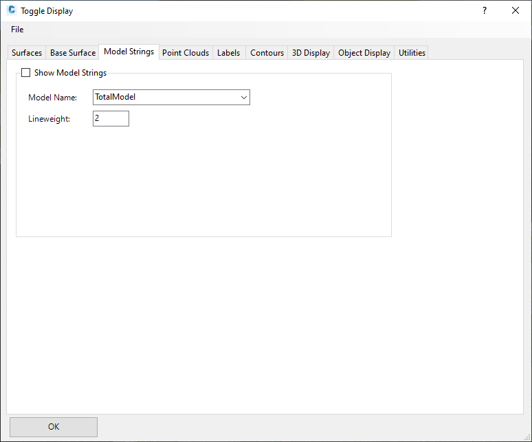
Model Strings
|
|
|
| Show Model Strings | Tick on to show the Model Strings in the Model Viewer. |
| Model Name | Select a Model from the dropdown whose strings are to be shown in Model Viewer. |
| Lineweight | Specify the thickness of the Lines that will be displayed in the Model Viewer. |
Point Clouds Tab
This tab is explained in the Point Cloud Setup command.
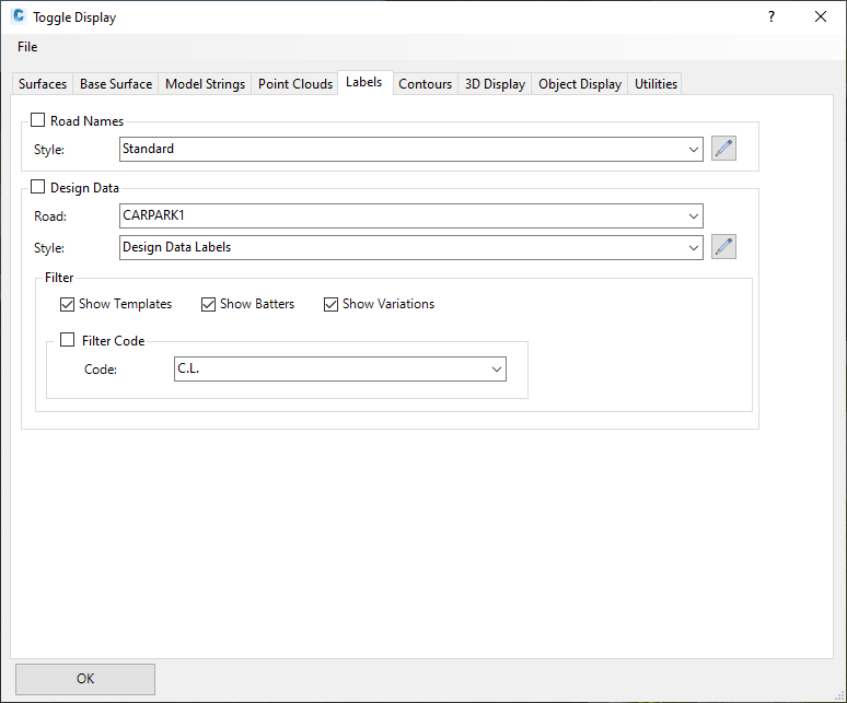
Labels Tab
|
|
|
|
Road Names |
On each road, a label displaying the road name can be shown. This label can be toggled on/off. |
| Style |
All label
styles are listed here and the user can select the
style used for the display of the road label. The label
style can be edited by pressing
|
|
Design Data |
For a specified road, the design data (from the Design Data Form) is displayed. Within Model Viewer, users can see templates assigned to a road, variations applied, along with other edits. These labels can be toggles on/off. |
| Name | Select the road to display design data labels for. |
| Style |
All label
styles are listed here and the user can select the
style used for the display of the design data labels. The
label style can be edited by pressing
|
|
Filter & Code Filter |
Rather than showing all design data information, users can toggle on/off the display of items such as templates, batters, or variations. Also, the user has the ability to filter the design data for a single design code (i.e. the LEB code). For example, this option would allow the user to see only variations that have been applied to the LEB code. |
|
OK |
Apply and exit. |
Contours Tab
|
|
|
|
Surface Name |
Lists all surfaces in the current project. In order to see the contours displayed, contours for the surface must be currently displayed in plan. |
| Lineweight | Allows the user to specify the lineweight of the contours to be displayed. Colour of the contours will be the same as the contours currently displayed in plan. |
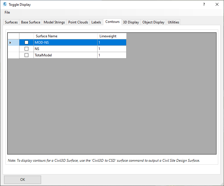
Note: At this stage, contours for Civil3D Surfaces cannot be displayed in Model Viewer. If you would like to display contours for a Civil 3D Surface, then it is recommended to convert the Civil 3D to a Civil Site Design Surface by using the C3D to CSD Surface command.
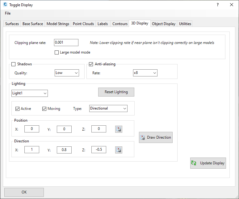
3D Display Tab
This tab controls many aspects of the environmental controls in Model
Viewer, such as shadow casing, lighting sources and anti-aliasing.
|
|
|
| Clipping Plane Rate | This establishes when Model Viewer detects that the camera is 'cutting' the surface or an object. If users find that the surface is being 'trimmed' when viewed at a driver/person position, reduce the Clipping Plane Rate by a factor of 10 (repeat this until trimming appears as expected) |
| Large Model Mode (beta) |
Civil Site Design has access to a beta release of a large
surface computational engine. If the surface is large,
this should improve performance and reduce refresh times. Currently this functionality is in beta - if it is found that there are stability issues this option should be turned off |
| Shadows | Toggle on to apply shadows based on the applied Lighting |
| Quality | Select from High, Medium or Low. The quality affects how much tesselation is seen in the shadow casting. Shadows will display on all surfaces and all objects. |
|
Anti Aliasing |
Control the rate of anti-aliasing |
| Rate | Choose from the dropdown pick list. |
|
Lighting |
|
| Pick List | Up to 4 light sources may be applied (named Light1, Light2, Light3 and Light4). When selected, the inputs below control the light behaviour |
| Reset Lighting | Reset the lighting to defaults (one overall ambient light source) |
|
|
|
| Active | Tick on to enable the lighting |
| Stationary |
Tick on to assume a stationary light source. Tick off to adopt a position and direction relative to the user position and direciton in Model Viewer |
| Type |
Three typs of light source can be applied: - Directional - Point - Spot |
|
|
|
| Position | Fill in the x, y and z fields for the lighting position |
|
|
|
| Direction | Fill in the x,y and z fields for the lighting direction |
|
Refresh Performance |
|
| Fast Refresh | The slowest part of running a refresh in Model Viewer is the re-calculation of the base surface when it is required to trim the triangulation. Users have the option to toggle off the trimming of the base surface to considerably increase the performance of Model Viewer refreshing. This option is recommended when working with really large terrain data or if only minor changes are expected to be made to the the surface models on refresh. |
| Cache | When the software first calculates the base surface (inclusive of trimming), the software will record this information to memory. So on each refresh to the model. the cached base surface is used rather than a re-calculated base surface. This is recommended when working with large detailed surface data or when the job is almost complete and the user is simply working in Model Viewer to perform sight distance checks, import 3d models, or when it is not required to completely re-calculate the base surface. |
| Apply Transparency | This option will turn off trimming of the base surface completely. The base surface will then be displayed with a transparency, so the user can still see design data that exists below the base surface. |
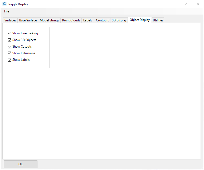
Object Display
|
|
|
|
|
|
| Show Linemarking | Toggles the display of Line Marking created in the Model Viewer. |
| Show 3D Objects | Toggles the display of 3D Objects shown in the Model Viewer. |
| Show Cutouts | Toggles the display of Cutouts shown in the Model Viewer. |
| Show Extrusions | Toggles the display of Extrusions shown in the Model Viewer. |
| Show Labels | Toggles the display of Labels shown in the Model Viewer. |
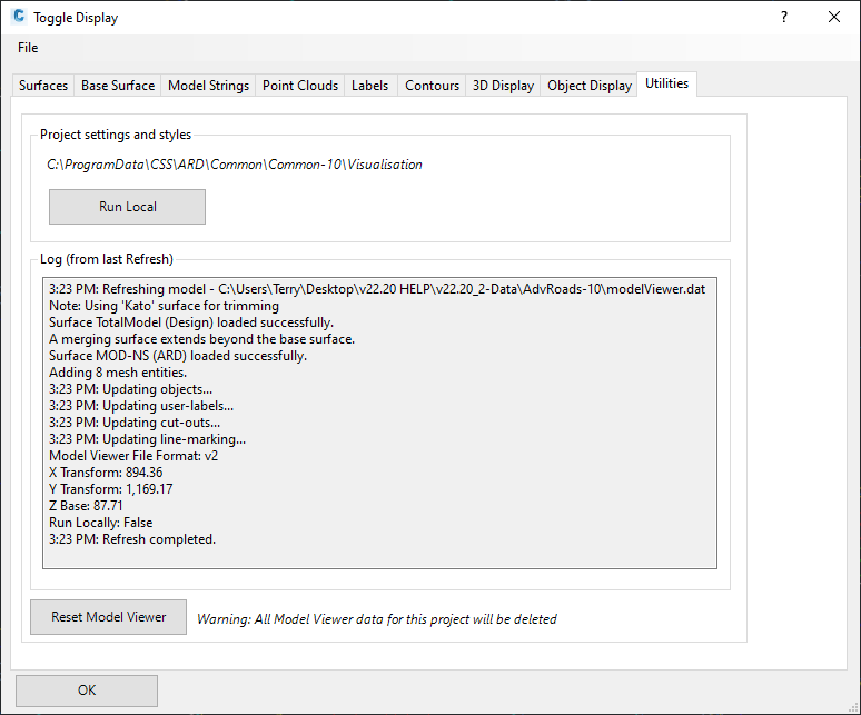
Utilities Tab
When Model Viewer starts, the settings (materials, design codes, labels, etc) will be read from the CSD Settings folder. The Utilities tab includes the option to set this project to copy in the settings and run them locally (from the current project). This makes them more portable (because they are in the current project data).
|
|
|
|
Project Settings and Styles |
Establish where Model Viewer resources the blocks, materials, sight distance tables, etc. |
| Save Path | The save path to the Model Viewer resources are shown. |
| Run Local/Run Global |
Run Local: Click on this button to store all the settings
required for this model, inside the -Data folder for the
drawing. Run Global: Click on this button to reference data stored in the CSD Settings folder |
|
Log |
This will display the processing steps of the last model Refresh. Useful for locating errors. |
| Reset Model Viewer |
This will delete all setup of Model Viewer for this project,
letting the user 'start afresh'. Note: All stored Model Viewer data (such as surfaces to display) will be deleted. |