Edit Pipe Properties
| Icon: |
|
| Menu: | CSD Pipes > Edit > Edit Pipe Properties |
| Ribbon: | Pipes Tab > Edit Panel > Edit Pipe Dropdown > Edit Pipe |
Introduction
This command allows for editing of a pipe - users are able to change the pipe type, set the number of parallel pipes and set the upstream and downstream levels.
Details
Upon selecting this command, at the Command prompt the user will be asked to "Locate Pipe to Edit".
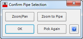
When a pipe is selected, the pipe will be highlighted and the following form is displayed (unless disabled in the Active Network Settings):
 |
|
| Zoom/Pan | Provides a way to zoom or pan around in the drawing. Use Mouse Wheel to Zoom/Pan. Press Enter/Esc to Finish. |
| Zoom to Pipe | Will zoom to the selected pipe, so that it fits within the screen. |
| OK | Select OK to continue. |
| Pick Again | Provides the option to select a different pipe, if the highlighted pipe is incorrect. |
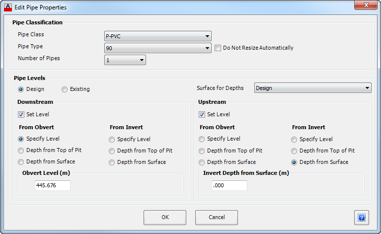
After a pipe is selected the following form is displayed (all options shown):
 |
|
| Pipe Classification | Set the pipe type, number of parallel pipes and whether the pipes should automatically be resized. |
| Pipe Class | Select the Pipe Class to be used for the pipe segment selected. |
| Pipe Type | Select the Pipe Type to be used for the pipe segment selected. |
| Number of Pipes | By default only a single pipe is used, however if multiple parallel pipes are required, select a number between 1 and 5. |
| Do Not Resize Automatically | This toggle is applicable for Drainage Networks only - in a drainage network the software determines the pipe size required based on the design inputs. If this box is checked, the pipe size set in the form is fixed (set by the user) and will not change based on the drainage calculations. |
| Pipe Levels | Set the pipe levels at each end. Users are able to override the automatic levels assigned by the software. |
| Design | Toggle this option if the pipe is able to be designed - users will be able to select whether to manually use Set Level to set the upstream/downstream levels or to use the software design controls. |
| Existing | Toggle this option if the pipe is an existing pipe - users will need to set the upstream and downstream levels of the pipe. |
| Surface for Depths | This box will only appear when Depth from Surface is selected in either of the Downstream or Upstream frames below. Pick the surface to use as a reference. |
| Downstream | Set downstream end of the current pipe segment. |
| Set Level | This option only appears if Design is selected above. When the box is unticked, the design level will be set by the software based on the design criteria. When the box is ticked, the invert level is able to be set by the user and controls are displayed below. |
| From Obvert | Toggle this option on to set the level of the pipe Obvert. Three methods of setting the level are provided: |
| Specify Level | Toggle this option to set a level. Enter a fixed level, in metres, in the box provided below. |
| Depth from Top of Structure | Toggle this option to set the level as a depth from the top of structure. Enter the depth (in metres) from top of structure in the box provided below. |
| Depth from Surface | Toggle this option to set the level as a depth from a surface. Enter the depth (in metres) from the Surface that can be selected above, in the box provided below. The Surface for Depths displays the surface used for levels. |
| From Invert | Toggle this option on to set the level of the pipe Invert. Three methods of setting the level are provided: Refer to Obvert (above) for details. |
| Upstream | Set the upstream end of the current pipe segment. All inputs are as for the Downstream. |
| OK | Apply and exit. |
| Cancel | Exit the form without making any changes. |