Label Styles
Icon: |
|
| Menu: | Alignments > Labels > Label Styles Surfaces > Labels > Label Styles Roads > Labels > Label Styles Pipes > Labels > Label Styles General > Labels > Label Styles |
| Ribbon: | Alignments Tab > Utilities Panel > Labels Dropdown > Label Styles Surfaces Tab > Utilities Panel > Labels Dropdown > Label Styles Roads Tab > Plan Production Panel > Labels Dropdown > Label Styles Pipes Tab > Plan Production Panel > Labels Dropdown > Label Styles General Tab > Labels Panel > Settings Dropdown > Label Styles |
Introduction
Label commands introduced in the V16 release of the product all use Label Styles to manage the display of label information in the drawing.
Label Styles manage the display of all of these labels. Label Styles are separated by the type of object they are intended to represent - this enables control of the the text 'properties' (information about the object the label relates to) and line 'connection' (as an example, vertical curve labels may need to be attached to the start or end of a vertical curve, or at the vertical intersection point (IP) location) to relate specifically to the object to which they are being applied.
Anatomy of a Label Style
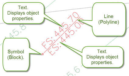
With few exceptions, a Label Style is made up of a collection of:
- Symbols (blocks)
- Text, and
- Lines (polylines).
One of the components added will act as the 'marker' to control the insertion point of the label. Some labels are able to be repositioned by the user - the 'marker' acts as the insertion point for the label. Some labels will update text information when the marker is repositioned (such as Surface labels) whilst others will only move the Label position (such as Elevations on Poly labels). Labels act as a 'group' when the 'marker' is moved, moving relative to the change in the marker position.
When a label is created, data is stored with the label to maintain information regarding the relative position and orientation of each of the components that makes up the label. When a component of the label is selected using CAD controls (such as grips) and repositioned, it will still remain part of the label and 'remember' the new position. Similarly, commands such as move and rotate will result in the component being updated and the manual edits 'remembered' by the label.
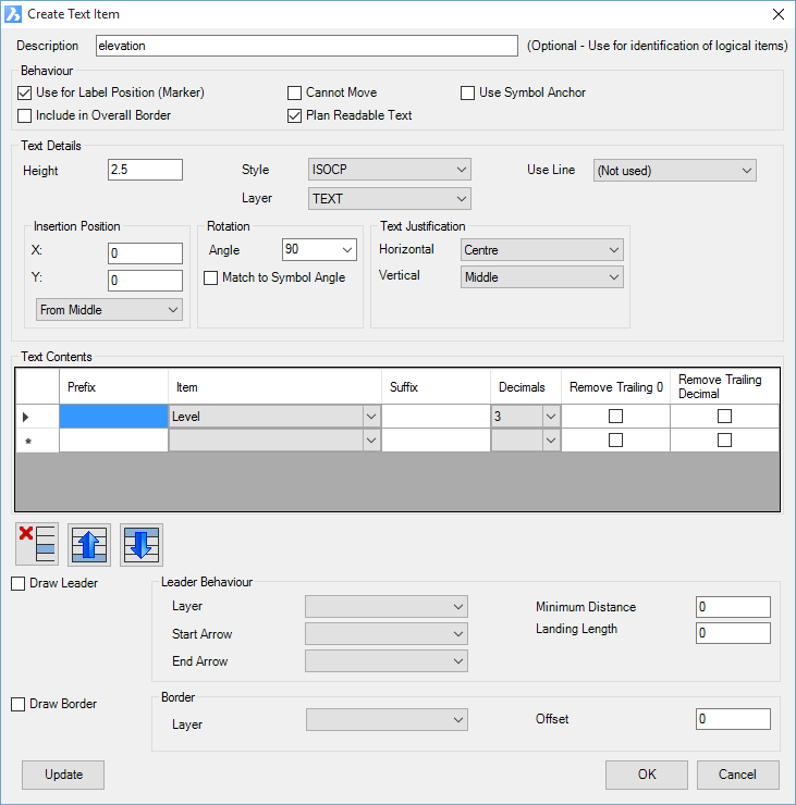
Text components may be 'attached' to a line so that the insertion, orientation and justification of the text is dependent on the line geometry.
Notes: For text to be associated to a Line entry, the Line entry must PRECEDE (come before) the Text entry/ies in the list of components, otherwise it will not use the Line geometry for the text position and rotation. If text is associated with a line, the X offset control is disabled for the text postion.
Label Editing
Some labels are able to be repositioned by the user (such as Surface Labels) - the Label Style assigns a 'Marker' to one of the label components, with movement of the 'marker' triggering a new location of the Label insertion (resulting in a recalculation of the text information in the label).
Below is an example of a Label Style being edited using AutoCAD grip edits - the 'marker' in this case is the symbol (block). The text objects are associated with the Line (polyline) geometry.
Updating Labels
Some labels will update when they are grip edited in the drawing. Labels are always updated when the Move Label command or the Update/Create Label commands are used in the respective label creation commands.
Typically, label text will not update automatically when the source object (eg: surface elevations) change. The Label ![]() Synchronise command should be used in these cases to update all Labels in the drawing.
Synchronise command should be used in these cases to update all Labels in the drawing.
When working with labels, it is recommended to run the ![]() Synchronise command whenever edits are made, such as:
Synchronise command whenever edits are made, such as:
- The source object (eg: surface) is edited which requires a recalculation/update of the text information
- The Label Style applied to the label in the drawing is edited
- Other moves are applied (eg: move, scale or rotate commands) and the label details are not updated (you must move the label Marker for text components of the label to udpate)
- The Drawing Annotation scale is changed - this is relevant for all labels that are set to read the Drawing Scale
- If it appears that any label/s are not describing the correct information
About Text Heights, Symbol Sizes and Line Lengths
It is recommended that all text heights, symbol sizes, offsets and line lengths be specified in mm (or in imperial situations, inch) units. When Labels are inserted into the drawing, users can specify a drawing scale to apply to the labels upon insertion (or set the labels to automatically react to the drawing annotation scale). The scale is applied to all values for the geometry, size and position of all components of the label.
Text Details - Static Text and Object (Property) Text
Each Text element can be set to include static (non-changing) text as well as object property text (text that reads information from the object to which it is attached).
Typically, the properties reference a specific attribute of the object (eg; for Surfaces, it might be required to include the surface elevation or surface slope), however some properties are conditional.
Examples of conditional text is surface cut and fill. If the text property includes a question mark (?) then it will only be applied if those conditions are met (including the associated prefix/suffix). A good example of this is for the surface label styles - text properties include Cut ? and Fill ?. If both properties are added to the text object, only one will display (depending on whether it is in a cut or fill condition).
Label Examples
Label Styles are categorised by the objects that they are to represent. Below are some Labels created for different object types:
| Relates to | Label Type/Command | Details | Sample | Availability |
| Surface | Surface Labels - Surface Elevations | Display surface elevations, including cut and fill | 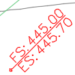 |
All |
| Surface Labels - Surface Slopes | Display instantaneous slope information for a surface |  |
All | |
| Surface Labels - 2 Point Slopes | Display AVERAGE slope calculated between two points, defined by the start and end of a Line element defined in the style Note: the Line must act as the Marker for this type of application. |
|
All | |
| Surface/Alignment | Elevations on Polyline | Display surface elevation information, calculated at a polyline vertex and text oriented to the polyline | 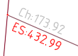 |
All |
| Alignment | Chainage (Station) on Polyline | Display alignment chainage information, calculated at a polyline vertex and text oriented to the polyline | 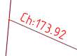 |
All |
| Chainage/Offset (Station/Offset) | Display alignment chainage(station) and information, calculated at a selected location in the drawing |  |
All | |
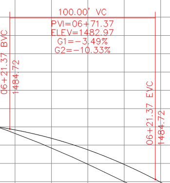
| Road | VC Details | Display string vertical geometry on the plan | 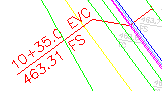 |
CSD Imperial |
| Multi String and String Labels | Display information on plan related to design codes on a String, such as elevation and code | 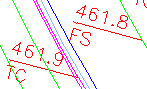 |
CSD Imperial | |
| Profile Views (USA) | Vertical Geometry Labels | Display vertical geometry information on the profile views. |
 |
All |
| Horizontal Geometry Labels | Display horizontal geometry information on the profile views. | 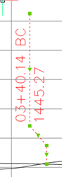 |
All | |
| Pipes | Network Labels - Pits | Display pit information |  |
All |
| Network Labels - Pipes | Display pipe information |  |
All | |
| House Connections | Display house connection information at start, end or middle of the house connection | 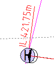 |
All | |
| Section Outputs | Plot Layers Sections | Display information in the section bands (eg: Design elevations, offsets, existing surface elevations, etc) | 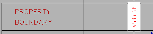 |
All |
| Plot Layers Sections - Surface Label | Display information on the section view itself for publishing section outputs | 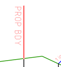 |
All |
Local vs Global Label Styles
The Label Styles used in a drawing are always local to that drawing/project only - known as local styles.
There is a specific command to create Global Label Styles - these styles are automatically propagated to new drawings/projects as local styles.
Use the Copy Label Styles command to copy between the current drawing (local) and the CSD Settings folder (global).
Label Style Process
Upon starting the command, the user is required to pick the type of Label Style to edit - this relates back to the objects that the Label Style is intended for.
Following selection of the type, the Label Style form displays. This form is, with few exceptions, the same regardless of the Label type (the same regardless of what object it's intended for)
Details
Upon selecting the command the following form is displayed:
|
|
|
|
List of Label Types |
Select an item. This lists each Label Type - the Label Type name of each is descriptive of both what the label is intended for as well as the name of the related Label command. Exceptions: - Pipes and Pits/Structures are label styles for the Network Labels command - Road String Codes are label styles for both the Multi String labels and String Labels commands |
|
OK |
Open the Label Style editor for the selected Label type |

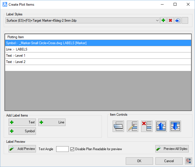
Following this selection the Label Style form displays:
|
|
|||||||||||||||||||||||||||||||||||||||||||||||||||||||||||||||||||||||||
|
Label Styles |
Pick a Label Style to edit | ||||||||||||||||||||||||||||||||||||||||||||||||||||||||||||||||||||||||
|
|
Create a new label style. A form will display to enter a new Label Style name. | ||||||||||||||||||||||||||||||||||||||||||||||||||||||||||||||||||||||||
|
|
Deletes the highlighted label style. A warning message will display to confirm deletion. | ||||||||||||||||||||||||||||||||||||||||||||||||||||||||||||||||||||||||
|
|
Opens a Windows Explorer type window to select another Label Style to copy, rename and import into the current Label Styles. By default, the path initially is set to the current drawing/project data directory. After selecting a Label Style to use, the user is prompted to set a name for this copied Label Style. It is then added to the Label Style listing for editing. |
||||||||||||||||||||||||||||||||||||||||||||||||||||||||||||||||||||||||
|
|
Creates a copy of the currently selected Label Style. User is prompted to name the new Label style. |
||||||||||||||||||||||||||||||||||||||||||||||||||||||||||||||||||||||||
|
Plot Items |
Lists all of the items (objects/components) that collectively represent the Label. Each of these items is an element of label display | ||||||||||||||||||||||||||||||||||||||||||||||||||||||||||||||||||||||||
|
List of Items |
Each added item is listed, with a basic description of the component type (Text, Line, Symbol). Double click on an entry to open it for editing |
||||||||||||||||||||||||||||||||||||||||||||||||||||||||||||||||||||||||
|
Add Label Items |
Allows for adding new components to the Label. | ||||||||||||||||||||||||||||||||||||||||||||||||||||||||||||||||||||||||
|
|
Adds a text component to the Label Style. Inputs are as follows
|
||||||||||||||||||||||||||||||||||||||||||||||||||||||||||||||||||||||||
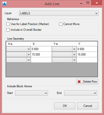
|
|
Adds a polyline to the Label Style. Inputs are as follows
|
||||||||||||||||||||||||||||||||||||||||||||||||||||||||||||||||||||||||
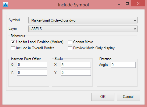
|
|
Adds a block to the Label Style. Inputs are as follows
|
||||||||||||||||||||||||||||||||||||||||||||||||||||||||||||||||||||||||
|
Item Controls |
Move label components and edit label components in the list. | ||||||||||||||||||||||||||||||||||||||||||||||||||||||||||||||||||||||||
|
|
Copy an entry |
||||||||||||||||||||||||||||||||||||||||||||||||||||||||||||||||||||||||
|
|
Edits an entry. The same forms will display as described above, based on the entry type. |
||||||||||||||||||||||||||||||||||||||||||||||||||||||||||||||||||||||||
|
|
Delete an entry |
||||||||||||||||||||||||||||||||||||||||||||||||||||||||||||||||||||||||
|
|
Move an entry up in the list | ||||||||||||||||||||||||||||||||||||||||||||||||||||||||||||||||||||||||
|
|
Move an entry down in the list | ||||||||||||||||||||||||||||||||||||||||||||||||||||||||||||||||||||||||
|
Label Preview |
Preview display before creation | ||||||||||||||||||||||||||||||||||||||||||||||||||||||||||||||||||||||||
|
|
Adds the current Label Style as a preview label in the drawing | ||||||||||||||||||||||||||||||||||||||||||||||||||||||||||||||||||||||||
|
Test Angle |
Type in a testing angle for the preview label | ||||||||||||||||||||||||||||||||||||||||||||||||||||||||||||||||||||||||
|
Disable Plan Readable for preview |
Tick on to disable | ||||||||||||||||||||||||||||||||||||||||||||||||||||||||||||||||||||||||
|
Preview All Styles |
Create all Label Styles as preview labels in the drawing. | ||||||||||||||||||||||||||||||||||||||||||||||||||||||||||||||||||||||||
|
OK |
Create/Update Label Style and exit. |
||||||||||||||||||||||||||||||||||||||||||||||||||||||||||||||||||||||||
|
Cancel |
Exit without change. |
||||||||||||||||||||||||||||||||||||||||||||||||||||||||||||||||||||||||
|
|
Enables panning in the drawing. Left click or press a keyboard button to return to the form. |
||||||||||||||||||||||||||||||||||||||||||||||||||||||||||||||||||||||||