Network Labels
Icon: |

 |
| Menu: |
Pipes > Labels > Legacy Labels > Network Labels
General > Labels > Legacy Labels > Network Labels |
| Ribbon: |
General Tab > Legacy Labels Panel > Create Labels Dropdown
> Network Labels |
Introduction
Network Labels enable the user to label a pipe network on plan, with the option to customise each label style. The user can customise the labels of the individual pipes and
structures, depending on requirements.
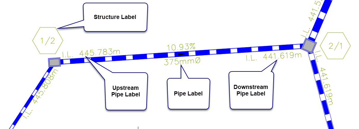
Both structures and pipes can be labelled at the same time using this command. There are enhancements to the label control (text offset, rotation, inclusion of leaders, borders, etc) with the label presentation being driven by Label Styles.
If any pipe network is updated, the Synchronise command should be run to update all labels.
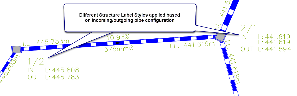
Users can have one Structure Label Style to apply to all
structures, or they can tick on the option 'Show structure styles for pipe
in/out' to enable different structure label styles to be applied to each pipe
in/out configuration.
Example Output - Single Label for all Structures
Example - Configured Structure Label Styles based on
pipe in/out configurations
Note: For basic network labelling, users can still use the Label Network (legacy)
command to label the pipe network.
Once a Description (Label Set) is assigned and labels created, the software will then provide a different form when the command is next run, enabling the user to create multiple Label Sets and select a Label Set to edit.
Details
Upon selecting the command the following form is displayed, unless the command has not been run before (in which case the form below is skipped). The user is required to choose an existing Label set or create a new one:
|
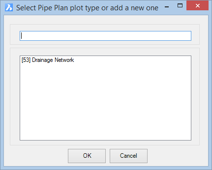
After typing in a NEW Descripiton (Label Set), or else picking a previously created Label Set, and clicking OK, the following form is displayed:
Structure Label Styles per pipe in/out configuration not enabled:
Structure Label Styles per pipe in/out configuration enabled:
|
|
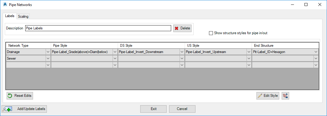
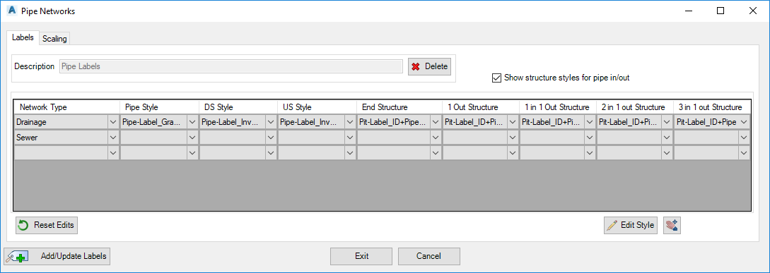
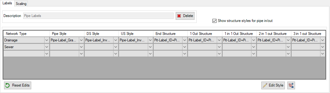
Labels Tab
|
This tab manages the parameters for the labels
|
|
|
|
|
|
Description
|
Group name of the Network Labels to be applied to the drawing
|
|

|
Delete the current Label Set Name with option to delete all associated label objects in drawing
|
|
Show structure styles for pipe in/out
|
Default toggle is off. When off (unticked), one column is provided to
assign a Structure Label Style to apply to all Structures
When ticked (on), 5 columns are displayed for the user to assign Structure Label
Styles for each of the 5 pipe inlet/outlet configurations. |
| Network & Style Selection |
|
|
Network Type
|
Select from Drainage or Sewer |
|
Pipe Style
|
Select a predefined Pipe Label Style The style will be
initially inserted centrally for each pipe |
|
DS Style
|
Select a predefined Pipe Label Style to apply at
the downstream end of the pipe |
|
US Style
|
Select a predefined Pipe Label Style to apply at
the upstream end of the pipe |
|
End Structure
|
Select a predefined Structure Style to apply to
structures in the drawing.
Note: if 'Show structure style for pipe in/out' is unticked, the Label Style
set in the End Structure column is applied to all structures in the drawing.
If ticked, the selected Label Style here will apply only to the most downstream
structure of each network. |
|
1 Out Structure
|
Select a predefined Structure Style to apply to the
most upstream structures in the network |
|
1 in 1 Out Structure
|
Select a predefined Structure Style to apply to
structures with one incoming and one outgoing pipe to the structure |
|
2 in 1 Out Structure
|
Select a predefined Structure Style to apply to
structures with two incoming and one outgoing pipe to the structure |
|
3 in 1 Out Structure
|
Select a predefined Structure Style to apply to
structures with three incoming and one outgoing pipe to the structure |
| Reset Edits |
Select to reset grip editted labels to default positions |
|
Edit Style
|
This opens the Label Styles command for Surface Labels |
| Pan |
Click to temporarly enable user panning in the
drawing. |
|
|
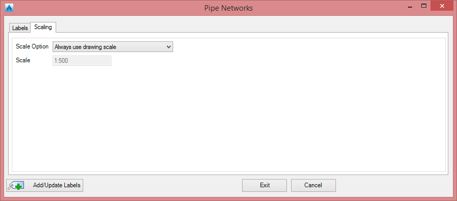
Scaling Tab
|
This tab manages the scaling of the labels within the drawing
|
|
|
|
|
|
Scale Option
|
Pick the following options |
| Always use drawing scale |
The label sizes are defined by the user annotation scale set in the drawing (CANNOSCALE) |
| Keep first drawing scale |
The drawing scale at the time of the Labels creation will be permanently stored & used regardless of future drawing scale changes. |
| User scale |
User can define the drawing scale of the labels using the box below |
|
Scale (1:x)
|
Select a list scale from the list or type a custom scale |
|
| Output |
|
 |
Add labels / update all labels within the current Description set in the drawing |
 |
Exit the Networks Labels command |