Set Road Defaults
Icon: ![]()
![]()
Menu: Roads > Settings > Set Road Defaults
Ribbon: Roads Tab > Design Panel > Create/Edit Road Drop-down > Set Road
Defaults
Introduction
While Civil Site Design is capable of a highly automated design process for a network of roads, to use this automation requires that the Designer assign section data to each road in the system prior to the automated design.
In the absence of specific cross-section assignments the program uses the default template specified in the
![]() Active Drawing Settings.
Active Drawing Settings.
Details
This command is used to vary the initial defaults for individual roads when using the
![]() Auto Road Creation
command.
Auto Road Creation
command.
The items in this form are only used at the time of creating a Road, so must be created PRIOR to creating the named road. This means that this option is generally taken after setting the defaults in the
![]() Active Drawing Settings.
Active Drawing Settings.
Note: After the road has been created, all these values can be edited through the
![]() Vertical Grading Editor or the
Vertical Grading Editor or the ![]() Road Data Editor. The main use of this form is to make it easy to set up the initial road network with a minimum
amount of work.
Road Data Editor. The main use of this form is to make it easy to set up the initial road network with a minimum
amount of work.
On starting the command the following form opens with the Default values to be used for all roads not otherwise changed.
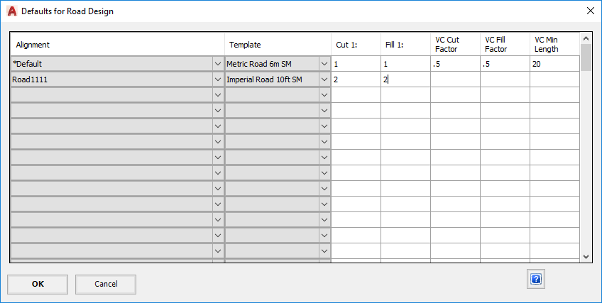 Using the pull down lists at the column headers and manual data entry, the Designer can set the parameters to be used for each road. |
|
| Alignment | Select the Alignment for which the row data applies |
| Template | Select the road template which defines the top surface section |
| Cut 1: | Define the slope of the Cut batters each side of the road in the form rise:run. |
| Fill 1: | Define the slope of the Fill batters each side of the road in the form rise:run. |
| VC Cut Factor | When a road is first created Civil Site Design performs an analysis of the existing surface along the alignment centreline and fits a design longitudinal section (profile) to the road. This and the following two parameters constrain the new design longitudinal section.
The Cut factor is the approximate maximum depth of cut. Increasing this factor generally means more cut, decreasing it means less. However, depending on the actual ground, it is possible for the cut to exceed this figure - hence it should be used as a guide only. |
| VC Fill Factor | The Fill factor is the approximate maximum depth of fill. Increasing this factor generally means more fill, decreasing it means less. However, depending on the actual ground, it is possible for the fill to exceed this figure - hence it should be used as a guide only. |
| VC Min Length | The VC factor sets the default VC length. |
| Notes on VC Factors | After the road and the VC has been created, use the option "Compute VC from Existing Data" on the Vertical Grading Editor to redo the VC fitting and also adjust the fitting parameters. |
| OK | Apply changes and exit the form. |
| Cancel | Exit the form without changing any data. |