Section Volumes
Icon: |
Introduction
This command allows the user to calculate sectional volumes (average end area) for the design cross sections of any String. The datum is calculated using the subgrade layers defined for each string and is then compared to the sampled surface including stripping.
Cut and fill areas are calculated and displayed for each section for user review. Closed polygonal areas are formed to represent cut and fill areas between the design and sampled/stripped surface.
Volumes are calculated using the Average End Area method. Reported volume at a section takes the cut and fill areas of the current and next section, averages the areas and multiplies by the distance between the sections to obtain the volume.
The section sampling of the string can be applied, a Named Section List can be selected for the cross sections used in the area and volume calucations.
Volume calculations use the string Design Data form inputs for applied Stripping and Cut/Fill Compaction factors.
By default, volume areas are calculated:
-
In Cut, between the bottom subgrade layer and the sampled surface (or stripping surface, where stripping is applied). Where there are no subgrade layers for a section, calculation is made to the design surface.
-
In Fill, between the bottom subgrade layer and the sampled surface (or stripping surface, where stripping is applied). Where there are no subgrade layers for a section, calculation is made to the design surface.
In situations where the design surface does not finish by intersecting with the sampled (or strip) surface, the software assumes a vertical (or near vertical) line connecting from the offset extents of the design to the sampled (or strip) surface. In cases where the design surface extents exceed the sampled surface, the sample surface is extended to match using the last section slope of the sampled surface.
For construction volume calculations, users can override:
-
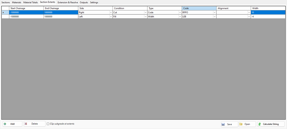
Section Extents: The width can be constrained left/right for calculating the extents for volumes. Users can control this using a Code (obtaining the datum from the code, or a width)
-
Extension and Resolve: The datum line can be extended beyond the subgrade edge, left and/or right, and include a slope projection from the extended edge to match to the surface/strip (this may represent an angle of repose for construction). If any entries are added, the software will stop auto resolving a closed area connection between the two surfaces. The user will need to manage cut and fill conditions both left and right of the centreline.
The user can override the default calculations to control how volumes are managed at the mutual extents of subgrades. This command is useful for calculating cross section based volumes for any two surfaces.
Design and Updating
This is a modeless form enabling design changes to be made with the form open. There is a calculate button to update the section volumes based on any changes made to the strings.
Interface Overview
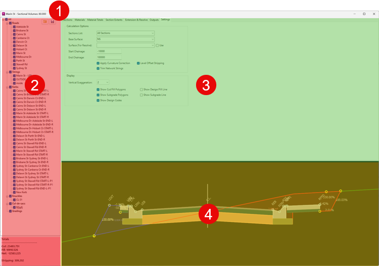
The Section Volumes form is divided into three core parts:
-
Currently selected String and Chainage being displayed
-
Left Side panel
-
From the left side users can select any String for volume reporting
-
Untick strings to exclude them from calculations and reporting
-
The bottom panel provides volume summary information fro the string
-
-
Right Side top panel
-
This includes a number of tabs
-
Chainages: Displays all calculated sections with the areas and volume calculations for cut and fill. Pick any section to display in the lower right panel
-
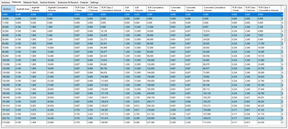
Materials: Displays all calculated sections wtih the areas and volume calculations for materials
-
Section Widths: Override the calculated seciton widths left and/pr right
-
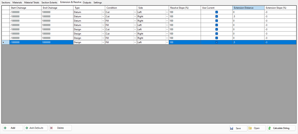
Extension and Resolve: Override the way the datum is calculated by extending left/right in cut/fill and adding a 'resolve' batter back to a surface
-
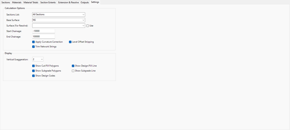
Settings: Manage the calculation process and the display controls
-
-
-
Right Side lower panel
-
Provides a graphical display of the selected string cross section including the cut/fill area, strip area, design codes, design top line subgrade line and design section materials
-
The user can elect to show subgrade layers, cut and fill areas as well as the design calculation lines used for generating the cut/fill areas.
-
Cut and Fill Representation - Sections Tab
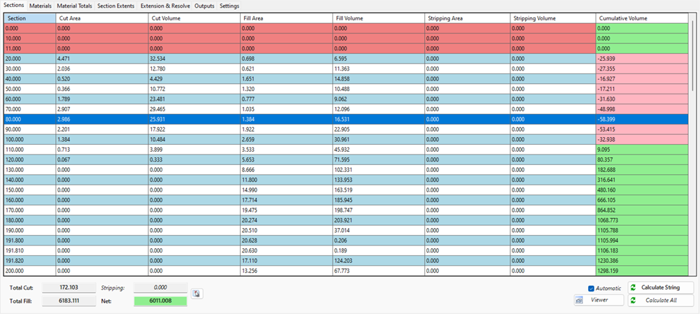
Cells describing a cumulative cut area/volume will be displayed with a pink background.
Cells describing a cumulative fill area/volume will be displayed with a green background.
Cells where there are no calculations (usually where Roads have been trimmed at intersections or cul-de-sacs) will display all cells in the row (except for cumulative volume) red.
Graphical Display
Graphically, cut ares can be shown with red outline and semi-transparent red infill, while fill areas can be shown with a blue outline and semi-tranparent blue infill.
The graphics display can also colour the section material areas, display the design codes and draw the calulation lines for the design (top) and subgrade (bottom). Circles will dipslay at subgrade calculation points.
The area will also textually be reported at the centroid of each area.

Where there is no batter setting the design to match back to the sampled surface, and in the absence of any Extension & Resolve controls, the software creates a closed area by drawing a vertical line to match the surfaces at the extents.
In cut, the subgrade will extend vertically from the outside bottom layer of a code until it meets either the subgrade (or design surface). It will otherwise trace the bottom subgrade layer until intersecting the sampled surface.
Form Heading - String and Chainage
The heading of the form lists the currently selected String and the currently selected Cross Section.
About Section Widths
By default, the full width of the design is used to calculate the cut/fill volume areas.
Users can use the Section Widths tab to restrict the widths left and right for calculation of only parts of the entire design cross section.
Section Widths can be set based on a Code and the user selects whether to apply the change in Cut or Fill (cut and fill conditions are caculated using the design surface at the offset set and compared with the sampled/strip surface).
The width left/right can be set by the Code, an Offset or using an Alignment. The width set for the subgrade calculation will, by default, be to the outside extents of the bottom layer of subgrade for the nearest outer code. The display of the section materials will be trimmed to the width set.
.
The is an option to tick on Clip Subgrade Extents. When ticked on, the subgrade offset is calculated exactly to match the extents set in the Section Width entry (a vertical slice of the section materials):

About Extension & Resolve
The Extension and Resolve tab provides designers control over what happens at the extents of the subgrade calculations. This is usually used for calculating construction volumes where a grader is needing to scrape a width beyond the design extents and form a batter to the surface matching the angle of repose for the material being excavated.
If any entries are applied, the user must manage what should happen both left and right in both cut and fill conditions (cut and fill are measured at the extents and using the design surface elevation)..
In fill, users are typically using the subgrade and then the Design surface to determine the fill extents.
In cut, users are typically using the subgrade surfae to determine the fill extents.
In the below image, an extension has been applied on the left and a resolve slope has been set.
The software uses the Section Width control to determine the subgrade extents, then:
-
In fill, uses the Design to manage added width (extension) and the resolve back to surface.
-
In cut, uses the Subgrade to manage added width (extension) and the resolve back to surface.

Managing Stripping
A strip depth can be applied to the string (this is applied via the Design Data form). When stripping is added, this form will display a copy of the surface at the strip depth and also display the strip volume areas.
By default (known as level offset stripping) the software essentially removes the strip material (to the extents of the design) to create a new 'sampled' surface where the strip depth is removed. This surface is then used to calculate all cut and fill areas for volumes.

Note in the above how the fill is calculated all the way to the bottom of the stripped depth.
Users can however opt to calculate the strip separately to the cut and fill calculations entirely. This is done by unticking the option of 'Level Offset Stripping'.

Additionally, users may wish to set the surface used for the calculation of fill, separate to the default of the sampled surface with the stripped material removed. Below is an example of this (note the difference in the fill (blue) areas stopping at the sampled surface):

Details
Upon selecting the command the following form is displayed:
|
|
|||||||||||||||||||||||||||||||||||||||||||||
|
Strings List |
Lists all Strings in the drawing. Select a String to view the section information for that String | ||||||||||||||||||||||||||||||||||||||||||||
|
[List of Strings] |
Separated by String type, click on any String to report the area/volume information for that string. |
||||||||||||||||||||||||||||||||||||||||||||
|
|
Opens a save file containing the list of Strings included (or excluded) for calculation | ||||||||||||||||||||||||||||||||||||||||||||
|
|
Save to file a list of included and excluded Strings for volume calculation | ||||||||||||||||||||||||||||||||||||||||||||
|
Totals Panel |
Information panel with total earthworks: Cut, Fill, Net and Stripping. Values are cubic metres or cubic feet (user environment) Panel displays red if the net result is in cut (negative) and green if the result is in fill (positive) |
||||||||||||||||||||||||||||||||||||||||||||
|
Sections Tab |
Lists all sections with bulk cut/fill earthworks reporting | ||||||||||||||||||||||||||||||||||||||||||||
|
[List on Inputs] |
Each row describes the areas and volumes caluclated from the current section to the next section. Areas in Red have no calculation applied (usually to describe trimming of side roads at intersections, and roads at cul-de-sacs). Tab display is as follows:
|
||||||||||||||||||||||||||||||||||||||||||||
|
Materials Tab |
Lists all material information per section | ||||||||||||||||||||||||||||||||||||||||||||
|
[List of Inputs] |
|
||||||||||||||||||||||||||||||||||||||||||||
|
Material Totals Tab |
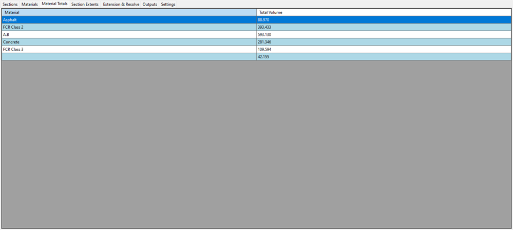
Lists all material totals | ||||||||||||||||||||||||||||||||||||||||||||
|
[List of Inputs] |
|
||||||||||||||||||||||||||||||||||||||||||||
|
Section Extents Tab |
Edit section extents for area/volume calculation | ||||||||||||||||||||||||||||||||||||||||||||
|
|
|
||||||||||||||||||||||||||||||||||||||||||||
|
Extension & Resolve Tab |
Edit the section for design of the datum | ||||||||||||||||||||||||||||||||||||||||||||
|
|
|
||||||||||||||||||||||||||||||||||||||||||||
|
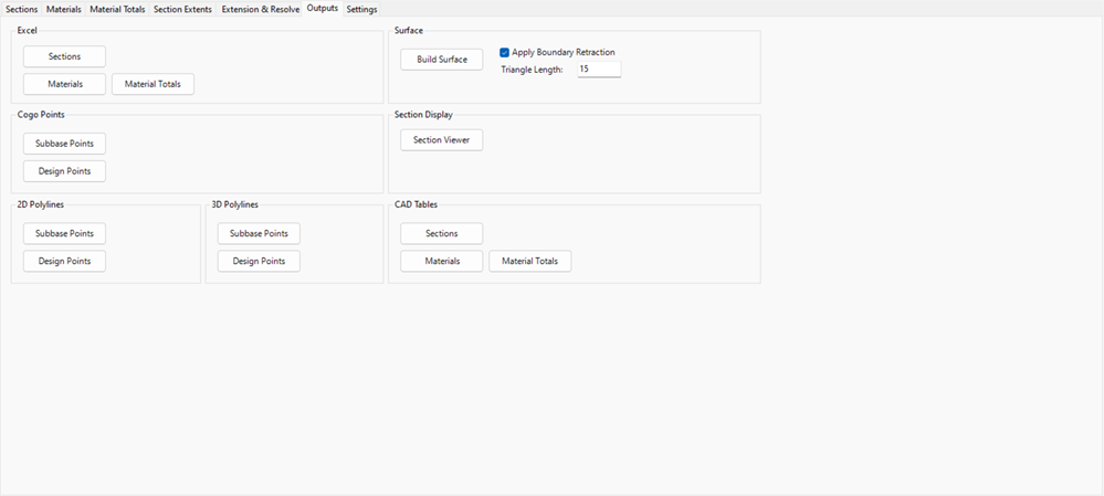
Outputs Tab |
Generate outputs | ||||||||||||||||||||||||||||||||||||||||||||
|
|
|
||||||||||||||||||||||||||||||||||||||||||||
|
Settings Tab |
Adjust settings for calculation and display | ||||||||||||||||||||||||||||||||||||||||||||
|
|
|
||||||||||||||||||||||||||||||||||||||||||||
|
[Graphic Display] |
Draws the sections, areas, subgrades and calculation lines. |
||||||||||||||||||||||||||||||||||||||||||||

