Create Alignment
Icon: ![]()
![]()
Introduction
Alignments are used throughout the software to manage the horizontal geometry for all String (vertical geometry) objects. All String centrelines require an alignment.
In Civil Site Design, users create alignments initially from any 2D polyline in the drawing. After creating the alignment, users are able to edit all curves as well as add, remove and move IP's (vertices).
As soon as a 2D polyline is selected as an alignment, the alignment lines/arcs/spirals are drawn and the alignment is labelled.
The Create Alignment form allows the user to:
- edit the alignment geometry
- manage the alignment display (both of the object and the labelling)
- generate alignment tables in the drawing
- generate curve tables in the drawing
General Process
- Draw 2D Polylines representing the alignment geometry
- Start this command
- Select the polyline
- Name the alignment, confirm/edit the labelling and confirm/edit alignment colours/layers
- Edit the geometry as required
- OK to exit and create/update the alignment
Notes:
- When an alignment is created or edited, users can select what Type of alignment they have created - this will control what type of String Object can be created from the alignment (eg: Road, kerb return, cul-de-sac, generic string, etc)
- The default display styles for the alignment object is managed
- The default display styles for the alignment labelling (annotation) is controlled in the Active Drawing Settings > Styles
- Labelling (annotation) Styles are managed locally in the drawing (local), but are inherited from the CSD Settings folder (global) when a new project is created. Users are able to set up the 'global' and 'local' styles.
- Alignment Table Styles and Curve Table Styles are managed in the CSD Settings folder only - when these styles are edited, the change will flow through to all other projects (current and future)
- Alignment names must not include any commas (,)
- The Create Alignment command cannot be used to edit an existing alignment - the Edit Alignment command must be used.
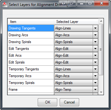
- Different layers can be assigned (with different colours) to identify the final alignment geometry as well as the edited and temporary alignment geometry.
Annotations vs Dynamic Labels
Alignments are annotated (labelled) by applying either:
- Dynamic Drawing Labels, combining Label Styles for select alignment geometry and the Selected Sections list to determine which chainages to apply, or
- (Legacy) Annotation Styles to particular geometry along the alignment and at user defined Major and Minor Chainages.
Dynamic Drawing labels include Label Styles, which can include a combination of text objects, polylines and blocks. The text inputs can include static text and alignment properties.
Legacy Annotation Labels can include a block on the alignment, a line extending from the alignment, text at a user set rotation and a border around the text.
Create Alignment vs. Edit Alignment
The Create Alignment form and Edit Alignment form are identical in terms of features, excepting that:
- During the Create Alignment process, users must type in a Name for the alignment
- The Name field is disabled from editing in the Edit Alignment command
- If the alignment is in use by a String, this will be highlighted in the Edit Alignment form
Details
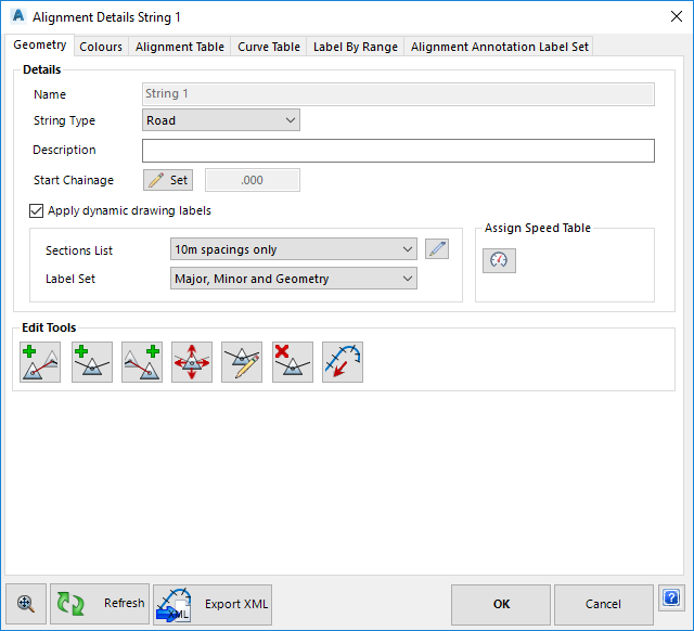
Upon selecting the command the user is prompted to select a polyline. Upon selecting a 2D polyline in the drawing the following form is displayed:
 |
|||||||||||||||||||||||||||||||||||||||||||||||||||||||||||||||||||||||
| Tabbed Controls | Use the tabs to manage the geometry, display and table outputs. Details for each aspect of the alignment are as follows | ||||||||||||||||||||||||||||||||||||||||||||||||||||||||||||||||||||||
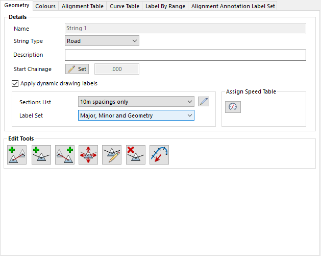
| Geometry | This tab controls the alignment geometry as well as alignment name and type. Details are as follows:
|
||||||||||||||||||||||||||||||||||||||||||||||||||||||||||||||||||||||
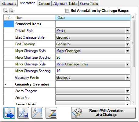
| Annotation (Legacy) | This tab controls the
LEGACY alignment annotation (labelling) along the alignment. Users can set different Annotation Styles to apply for select geometry along the alignment, as well as regular chainage intervals (major and minor). Details are as follows:
|
||||||||||||||||||||||||||||||||||||||||||||||||||||||||||||||||||||||
| |
Loads a saved Alignment Annotation Set. Upon selecting this command the user will be provided with a list of locally saved Annotation Sets to apply to the alignment. Note: This command is not relevant when Set Annotation by Chainage Ranges is selected. The CSD Settings are used to populate the local list of Annotation Sets when a new project is created. |
||||||||||||||||||||||||||||||||||||||||||||||||||||||||||||||||||||||
| |
After setting up Annotation Label Styles to apply for each item of the alignment, users can save this collection as an Alignment Annotation Set using this button. The Annotation Set will be saved locally to the project. Note: Users must use another command to transfer their project settings for alignment labelling across to the CSD Settings Folder, so it's available in all future projects. |
||||||||||||||||||||||||||||||||||||||||||||||||||||||||||||||||||||||
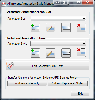
| |
This opens the Alignment Annotation Style Manager as shown below:
The details of this form and commands is covered in the |
||||||||||||||||||||||||||||||||||||||||||||||||||||||||||||||||||||||
| |
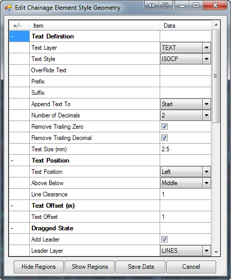
This opens the currently selected Annotation Style (from the Annotation Labelling List) for editing. Editing done to this style affects all alignments with annotations using this style. A view of the form is shown below:
The details of this form and commands is covered in the Note: This command is not relevant when Set Annotation by Chainage Ranges is selected. |
||||||||||||||||||||||||||||||||||||||||||||||||||||||||||||||||||||||
| Click to enable editing of individual labels along the alignment. Alignment annotation (label) positions and angles are set relative to the alignment location and chainage.
Upon selecting this command, the user is prompted to select an alignment annotation (label) in the drawing. Upon selecting an annotation (label) the command line reports the Chainage annotation selected for editing and user is prompted in the command line with the following options:
|
|||||||||||||||||||||||||||||||||||||||||||||||||||||||||||||||||||||||

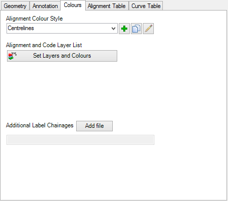 |
|||||||||||||
| Alignment Colour Style | The Alignment Colour Style sets out the layers to be applied to the alignment in the drawing and during editing. Users can create as many Alignment Colour Styles as desired, then apply them to different alignments. These styles are saved locally to the current project. Note: the Global Colour Settings command can be used to save and edit the colour styles in the CSD Settings - the CSD Settings are copied to the project when it is started. Use the pick list to select the colour scheme to apply |
||||||||||||
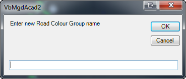
| |
Click to create a new Alignment Colour Style file. Upon clicking this button the prompts will be as follows:
|
||||||||||||
| |
Click to create a copy of the current Alignment Colour Style file. Upon clicking this button the user is prompted to set a new name for the copied style - form details as above. | ||||||||||||
| |
Click to edit the currently selected Alignment Colour Style. A form will display to confirm the style to edit. Inputs are as follows:
|
||||||||||||
| Set Layers and Colours | Allows the user to make layers to use in the display of the alignment as well as for the display of plan drafting in the drawing. Inputs are as follows:
|
||||||||||||
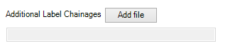
| Additional Label Chainages | Allows the user insert Extra Alignment Chainages from a text file. Before proceeding, the user is required to create a text file which additional chainages created to add to the chainage list. The following example shows additional chainages that area required on a seperate line. This file should be saved in the drawing data folder. |
||||||||||||
 |
|||||||||||||
| To add a new chainage file, click Add file | |||||||||||||
 |
|||||||||||||
| The user is require to pick a Chainage File (*.txt) | |||||||||||||
 |
|||||||||||||
| On completion, the alignment will automatically add in the new chainages. | |||||||||||||
 |
|||||||||||||
| The user can update this file and continually add more chainages. To restore the the new chainages to the alignment the user must use Edit Alignment &
|
|||||||||||||

 |
|||||||||
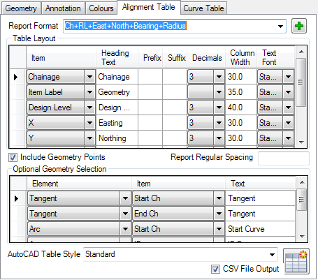
| Report Format | All alignment tables are saved as a Report. Users can create as many Reports as a desired for different table outputs. Each Report includes the columns of data required, the table layout and the geometry information to include. Tables are outputted as AutoCAD Table objects and/or as a .csv file. Pick a desired Report format. Note: All Report Formats are saved to the CSD Settings folder - as changes are made these are saved to the global settings and will affect all current and future projects when opened. |
||||||||
| |
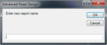
Click to create a new Report format. Upon clicking this button the prompts will be as follows:
|
||||||||
| Table Layout | Users can set up the columns of data required in the table and the table formatting. Each line in the list represents a column of data. Top row is first column, second row is second column, etc. | ||||||||
| Item | Select a property of the alignment. Properties are as defined in the list. | ||||||||
| Heading Text | Type in the column heading | ||||||||
| Prefix | Put a prefix on the selected property | ||||||||
| Suffix | Put a suffix on the selected property | ||||||||
| Decimals | For numeric property values, set the number of decimal places to display | ||||||||
| Column Widths | Sets the column width. Leave blank for a default width as set in the AutoCAD table style. Note: the Coloumn Width column does not display if Separate Table for Each Curve is ticked ON. |
||||||||
| Text Font | Select the font style to use for the column | ||||||||
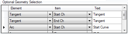
| Include Geometry Points | Tick this ON if it is desired to report chainages at geometry points along the alignment. If ticked on, the user is able to set up which geometry element/s (tangent, curve, spiral) to document in the table and what part of the geometry to report. In this list, users can assemble what information along the alignment is important (eg: start chainages at tangents, arc start/end chainages, etc). Inputs are as follows:
|
||||||||
| Report Regular Spacing | If it is desired to report details at regular chainage intervals, type in a spacing value Note: It is not recommended to tick on Include Geometry Points as well as specify a regular spacing. The row order is regular spacings first, then geometry points. |
||||||||
| AutoCAD Table Style | Set the AutoCAD Table Style to apply in the AutoCAD table output | ||||||||
| CSV File Output | Tick on to create a .csv file of the alignment table at the time of creating the alignment table. Note: By default, separate XML files are output for the alignments and DTM's and are saved to the location of the Data folder, in a folder named Temp. |
||||||||
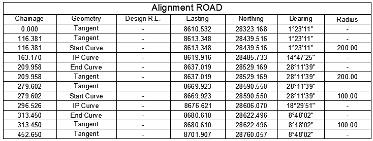
| Creates an AutoCAD table in the drawing, if none exists for the selected road and road format. If a table already exists, this command updates the contents. If the CSV file output is ticked on, a .csv file will also be created. User may be prompted to select a location for the table. Example output:
|
|||||||||
 |
|||||||||
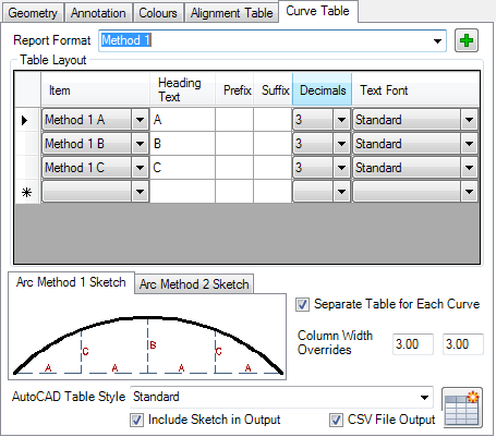
| Report Format | All alignment tables are saved as a Report. Users can create as many Reports as a desired for different table outputs. Each Report includes the columns of data required, the table layout and the geometry information to include. Tables are outputted as AutoCAD Table objects and/or as a .csv file. Pick a desired Report format. Note: All Report Formats are saved to the CSD Settings folder - as changes are made these are saved to the global settings and will affect all current and future projects when opened. |
||||||||
| |
Click to create a new Report format. Upon clicking this button the prompts will be as follows:
|
||||||||
| Table Layout | Users can set up the columns of data required in the table and the table formatting. Each line in the list represents a column of data. Top row is first column, second row is second column, etc. | ||||||||
| Item | Select a property of the alignment. Properties are as defined in the list. There are a collection of standard methods for setout of arcs - the details of these are as displayed in the Arc Method (No.) Sketch tabs. Review the sketch to relate the geometry being reported to the Item property. |
||||||||
| Heading Text | Type in the column heading | ||||||||
| Prefix | Put a prefix on the selected property | ||||||||
| Suffix | Put a suffix on the selected property | ||||||||
| Decimals | For numeric property values, set the number of decimal places to display | ||||||||
| Column Widths | Sets the column width. Leave blank for a default width as set in the AutoCAD table style. Note: the Coloumn Width column does not display if Separate Table for Each Curve is ticked ON. |
||||||||
| Text Font | Select the font style to use for the column | ||||||||
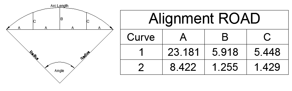
| Arc Method Sketches | This is a tabbed panel displaying standard curve layout methods. At the time of outputting the curve table, the currently highlighted Arc Method can be included as a block in the drawing. | ||||||||
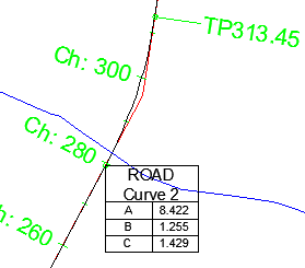
| Separate Table for Each Curve | Tick this ON to create an AutoCAD table for each curve. When ticked on:
Examples: Ticked On:
Ticked off: |
||||||||
| Column Width Overrides | If Separate Table for Each Curve is ticked on, these become active. Type in the first column width for the Heading and the second column width for the data/text | ||||||||
| AutoCAD Table Style | Set the AutoCAD Table Style to apply in the AutoCAD table output | ||||||||
| Include Sketch in Output | Tick this ON to include a block in the drawing (for the Arc Method highlighted in the form) at the time of creating the AutoCAD tabl. | ||||||||
| CSV File Output | Tick on to create a .csv file of the alignment table at the time of creating the alignment table. Note: By default, separate XML files are output for the alignments and DTM's and are saved to the location of the Data folder, in a folder named Temp. |
||||||||
| Creates an AutoCAD table in the drawing, if none exists for the selected road and road format. If a table already exists, this command updates the contents. If the CSV file output is ticked on, a .csv file will also be created. User may be prompted to select a location for the table. | |||||||||
 |
|
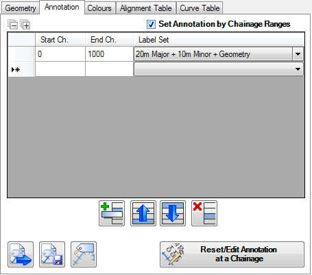
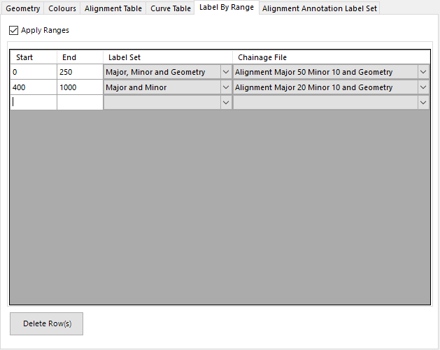
| Apply Ranges | Tick on to apply Ranges for labelling the alignment |
| Start | Start Chainage to apply a Label Set and Named Section List |
| End | End Chainage to apply a Label Set and Named Section List |
| Label Set | Pick list of Alignment Annotation Label Sets that can be applied to the alignment |
| Chainage File | Pick the Named Section List to apply. This contains all the chainages and the geometry types that could possibly be labelled. From these, the Alignment Annotation Set determines which geometry types to use for labelling |
|
Delete Row(s) |
Deletes selected row/s in the list |
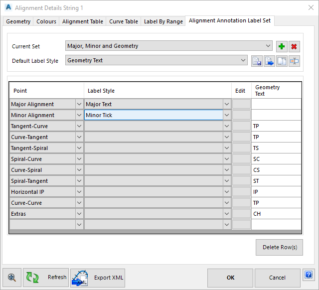
| Current Set | Label Set to edit |
| Add | Create a new label set |
| Delete | Delete the current label set |
| Default label Style | Default label style to apply to selected geometry types to label |
|
Save to Settings |
Save the Annotation Label Set to the CSD Settings folder to enable copy onto another string |
|
Load Settings |
Load a saved Annotation Label Set |
| Copy Settings | Make a copy of the current Annotation Label Set for the current drawing |
| Rename | Allows rename of the Label Set |
|
List of Geometry Types |
Select geometry to label on the alignment |
|
Point |
Select the geometry type from the picklist. Major Alignment and Minor Alignment inputs are at the bottom of the list. All inputs match up with Types that can be set in the Named Section List. |
|
Label Style |
Picklist of Label Styles to use to display the label |
|
Edit |
Opens the Label Style editor to edit Alignment type label styles |
|
Geometry Text |
Users can add a 'Geometry Text' property in the Label Style. If this is done, then typing into this field will populate this property with the typed in text. This minimises the number of label styles for alignments, where the only difference is the geometry text portion. |
|
Delete Row(s) |
Deletes selected row/s in the list |
Note: By default, separate XML files are output for the alignments and DTM's and are saved to the location of the Data folder, in a folder named XMLExchangeFiles. OK Save and exit Cancel Exit the form without change
Add any notes about the output controls and any special conditions.