Open Cross Section
Icon: ![]()
Introduction
Civil Site Design supports the opening of multiple cross section windows for any string.
This command allows the designer to open a new cross section window for any selected CSD object. This window will display the cross section design at the user nominated chainage for the selected CSD object. After starting the command, the designer needs to select the CSD object (eg: Road) and the chainage to display.
The Cross Section Window is also accessible from:
- The Vertical Grading Editor Window. When opening a cross section window from the Vertical Grading Editor Window, the chainage of the cross section window can be set to react to a right mouse button click in the Vertical Grading Editor Window. Users hover the mouse pointer near a sampled chainage in the Vertical Grading Editor window and click on the right mouse button to view that cross section in the Cross Section Window.
- The Design Data Form, and
- The Model Viewer. Right click in the vicinity of a string and use the shortcut menu.
Interface
The cross section includes the following components:
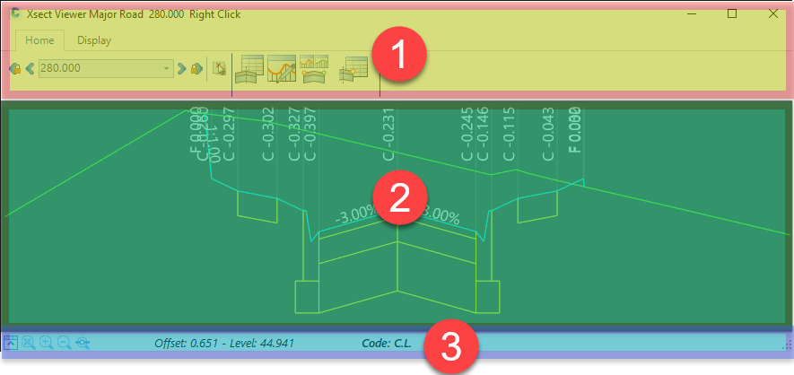
- Ribbon Area (Top)
- Navigate chainage, access vertical and cross section design forms and manage display
- Chainage selection. This is controlled by the navigation buttons at the top of the form:
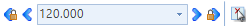
- hover in the Ribbon Area and roll the mouse buttton up/down to automatically increment through the chainages.
- Graphical Display Area
- Displays the existing and design sections, both graphically and textually.
- Zoom (roll middle mouse button) and pan (hold down middle mouse button)
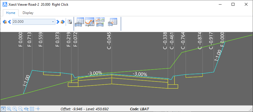
- Right click near a code to enable Direct Section Editing:
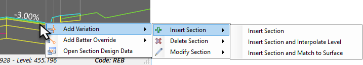
Direct Section Editing allows users to edit code positions horizontally and/or vertically, edit batter/daylight conditions or open the Section Design Data form for the current cross section.
Note: All actions available in the Direct Section Editor shortcut menu are reflected in the Design Data form. Changes to cross sections in the Section Design Data form are changing entries in the Design Data form.
- Information Display Area (Bottom)
-
 Minimise/Maximise Ribbon
  Zoom extents
 Zoom in
 Zoom out
 Zoom to
section in the drawing
Zoom to
section in the drawing- Details the nearest code
- Details the exact elevation and distance of the mouse pointer location.
-
 Enable a Grid Display
 -
 Change the tracker from a mouse to crosshairs
-
Display Controls
Users are able to configure the information displayed in the Cross Section Window, including the inclusion of objects in the view such as other Strings/Profiles, Alignments, CSD Pipes and selected AutoCAD objects. Whilst this can typically be configured on each cross section window displayed, defaults can also be set for cross section windows when they are opened via the following CSD commands:
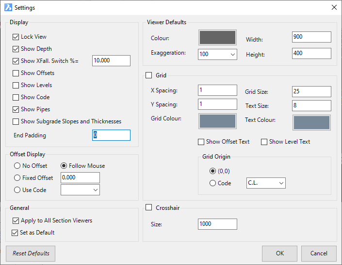
 Display 'Settings - this sets the default textual information to display in the cross section window as well as other controls
(including default display of Grid Lines and Crosshairs)
Display 'Settings - this sets the default textual information to display in the cross section window as well as other controls
(including default display of Grid Lines and Crosshairs) Object Display - this sets any objects to show on the cross section by default (eg: show alignments, strings, etc)
Marker Display in the Drawing
The active cross section is highlighted with a marker in the drawing. This marker is managed via a block in the Civil Site Design Settings (CSD Settings) folder. Users are able to replace this drawing block as desired. The CSD Settings folder can be opened in Windows Explorer via the Open Settings Folder command in the General menu/ribbon. The block is named XSECTACTIVE.dwg.
As the mouse if moved across a cross section window, a line will track the mouse location, displaying perpendicular to the section in the drawing.
About Direct Section Editing and the Section Design Data Form
It is often helpful to be able to do two things when viewing a particular cross section in the Cross Section Window:
- Be able to force change to the cross section Code/s, affecting that cross section chainage (and potentially a range of chainages). The change may be to delete a Code, insert a new Code, change the width/slope of a Code, change a Code offset to match an alignment, or set a Code to adopt the offset and elevation of another String.
- See the applied Template, Variations and Batter overrides applied at a particular cross section
Direct Section Editing delivers on point number 1 - users can right click to the nearest Code on the cross section window and execute a Variation related to that Code, or apply a Batter Override. A form will display following right click and an action selection, for the user to confirm what change is required and over what chainage range.
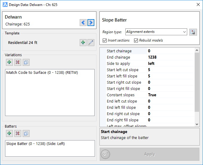
The Section Design Data form delivers on point number 2 - when opened, it will display the template applied, all Variations and Batter Overrides that apply at that chainage. Changing the section being viewed (by looking at a different chainage) will update the details automatically in the Section Design Data form. Users can see all changes applied to a cross section (template, variations and batter slope overrides) at any chainage.
In the above cases, the software is directly adding/editing entries in the Design Data form. The Design Data form stores all changes applied via the cross section window.
Details
After starting the command, select a CSD Object (by clicking on/near the alignment) and then click on the nearest chainage. The following form will be displayed:
 |
|||||||||||||||||||||||||||||||||||||||||||||||||||||||||||||||||||||||||||||||||||||||||||||||||||||||||||||||||||||||||||||||||||||||||||||||||||||||||||||||||||||||||
| RIBBON TABS | |||||||||||||||||||||||||||||||||||||||||||||||||||||||||||||||||||||||||||||||||||||||||||||||||||||||||||||||||||||||||||||||||||||||||||||||||||||||||||||||||||||||||
| Home Tab | 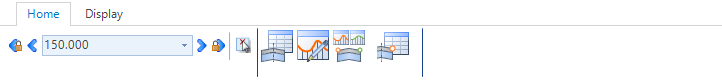 |
||||||||||||||||||||||||||||||||||||||||||||||||||||||||||||||||||||||||||||||||||||||||||||||||||||||||||||||||||||||||||||||||||||||||||||||||||||||||||||||||||||||||
| Chainage Selection Tools | |||||||||||||||||||||||||||||||||||||||||||||||||||||||||||||||||||||||||||||||||||||||||||||||||||||||||||||||||||||||||||||||||||||||||||||||||||||||||||||||||||||||||
| |
Change all open cross section windows to display the previous sampled cross section chainage. | ||||||||||||||||||||||||||||||||||||||||||||||||||||||||||||||||||||||||||||||||||||||||||||||||||||||||||||||||||||||||||||||||||||||||||||||||||||||||||||||||||||||||
| |
Change the cross section window to show the next sampled cross section chainage. | ||||||||||||||||||||||||||||||||||||||||||||||||||||||||||||||||||||||||||||||||||||||||||||||||||||||||||||||||||||||||||||||||||||||||||||||||||||||||||||||||||||||||
| Chainage Dropdown | Displays the current chainage being shown. Dropdown list to select any chainage | ||||||||||||||||||||||||||||||||||||||||||||||||||||||||||||||||||||||||||||||||||||||||||||||||||||||||||||||||||||||||||||||||||||||||||||||||||||||||||||||||||||||||
| |
Change the cross section window to show the next sampled cross section chainage. | ||||||||||||||||||||||||||||||||||||||||||||||||||||||||||||||||||||||||||||||||||||||||||||||||||||||||||||||||||||||||||||||||||||||||||||||||||||||||||||||||||||||||
| |
Change all open cross section windows to display the next sampled cross section chainage. | ||||||||||||||||||||||||||||||||||||||||||||||||||||||||||||||||||||||||||||||||||||||||||||||||||||||||||||||||||||||||||||||||||||||||||||||||||||||||||||||||||||||||
| |
Pick a cross section from the drawing to display | ||||||||||||||||||||||||||||||||||||||||||||||||||||||||||||||||||||||||||||||||||||||||||||||||||||||||||||||||||||||||||||||||||||||||||||||||||||||||||||||||||||||||
| |
Opens the |
||||||||||||||||||||||||||||||||||||||||||||||||||||||||||||||||||||||||||||||||||||||||||||||||||||||||||||||||||||||||||||||||||||||||||||||||||||||||||||||||||||||||
| |
Opens the |
||||||||||||||||||||||||||||||||||||||||||||||||||||||||||||||||||||||||||||||||||||||||||||||||||||||||||||||||||||||||||||||||||||||||||||||||||||||||||||||||||||||||
| |
Opens the Vertical Grading Editor window for every String that is associated to the current String (by way of Varation). | ||||||||||||||||||||||||||||||||||||||||||||||||||||||||||||||||||||||||||||||||||||||||||||||||||||||||||||||||||||||||||||||||||||||||||||||||||||||||||||||||||||||||
| |
Opens the Section Design Data Form. Note: All inputs in the Section Design Data form are saved to the Design Data Form. Upon selecting this command the following form is displayed:
|
||||||||||||||||||||||||||||||||||||||||||||||||||||||||||||||||||||||||||||||||||||||||||||||||||||||||||||||||||||||||||||||||||||||||||||||||||||||||||||||||||||||||
| Display Tab | 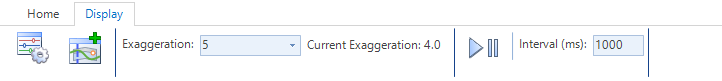 |
||||||||||||||||||||||||||||||||||||||||||||||||||||||||||||||||||||||||||||||||||||||||||||||||||||||||||||||||||||||||||||||||||||||||||||||||||||||||||||||||||||||||
| |
This command enables user control over what is displayed in the cross section window. Upon selecting this command the following form is displayed:
|
||||||||||||||||||||||||||||||||||||||||||||||||||||||||||||||||||||||||||||||||||||||||||||||||||||||||||||||||||||||||||||||||||||||||||||||||||||||||||||||||||||||||
| |
This command enables additional objects/data to be displayed on the cross section windows. The form layout and details are described in the |
||||||||||||||||||||||||||||||||||||||||||||||||||||||||||||||||||||||||||||||||||||||||||||||||||||||||||||||||||||||||||||||||||||||||||||||||||||||||||||||||||||||||
| Exaggeration | Pick list to select the desired vertical exaggeration. | ||||||||||||||||||||||||||||||||||||||||||||||||||||||||||||||||||||||||||||||||||||||||||||||||||||||||||||||||||||||||||||||||||||||||||||||||||||||||||||||||||||||||
| Current Exaggeration | Displays the actual vertical exaggeration being applied to the cross section window. | ||||||||||||||||||||||||||||||||||||||||||||||||||||||||||||||||||||||||||||||||||||||||||||||||||||||||||||||||||||||||||||||||||||||||||||||||||||||||||||||||||||||||
| Play Forward | Allows the user to auto scroll through sections in a forward direction | ||||||||||||||||||||||||||||||||||||||||||||||||||||||||||||||||||||||||||||||||||||||||||||||||||||||||||||||||||||||||||||||||||||||||||||||||||||||||||||||||||||||||
| |
Press to play through sections and again to pause/stop. | ||||||||||||||||||||||||||||||||||||||||||||||||||||||||||||||||||||||||||||||||||||||||||||||||||||||||||||||||||||||||||||||||||||||||||||||||||||||||||||||||||||||||
| Interval (ms) | Type in a time interval between chainages, in milliseconds. Note: actual speed of cycling through chainages may be limited by the drawing speed/processing of the computer. Recommended: 500. |
||||||||||||||||||||||||||||||||||||||||||||||||||||||||||||||||||||||||||||||||||||||||||||||||||||||||||||||||||||||||||||||||||||||||||||||||||||||||||||||||||||||||
| GRAPHICAL DISPLAY AREA | |||||||||||||||||||||||||||||||||||||||||||||||||||||||||||||||||||||||||||||||||||||||||||||||||||||||||||||||||||||||||||||||||||||||||||||||||||||||||||||||||||||||||
 As well as displaying the cross section string design, sampled surface, (optionally) pipes and other objects, users can also initiate changes to the cross sections. |
|||||||||||||||||||||||||||||||||||||||||||||||||||||||||||||||||||||||||||||||||||||||||||||||||||||||||||||||||||||||||||||||||||||||||||||||||||||||||||||||||||||||||
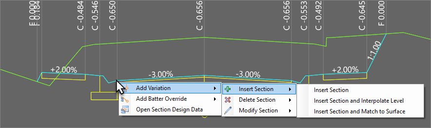
| Right Click (Direct Section Editing) | Right click near a Code to activate the Direct Section Editing shortcut menu. Direct Section Editing facilitates changes to the cross section, at that chainage and/or across a chainage range. Inputs are as follows:
|
||||||||||||||||||||||||||||||||||||||||||||||||||||||||||||||||||||||||||||||||||||||||||||||||||||||||||||||||||||||||||||||||||||||||||||||||||||||||||||||||||||||||
Once an option is selcted, the Direct Section Edit form will display:
|
|||||||||||||||||||||||||||||||||||||||||||||||||||||||||||||||||||||||||||||||||||||||||||||||||||||||||||||||||||||||||||||||||||||||||||||||||||||||||||||||||||||||||
| INFORMATION DISPLAY AREA | |||||||||||||||||||||||||||||||||||||||||||||||||||||||||||||||||||||||||||||||||||||||||||||||||||||||||||||||||||||||||||||||||||||||||||||||||||||||||||||||||||||||||
As well as displaying the cross section string design, sampled surface, (optionally) pipes and other objects, users can also initiate changes to the cross sections. |
|||||||||||||||||||||||||||||||||||||||||||||||||||||||||||||||||||||||||||||||||||||||||||||||||||||||||||||||||||||||||||||||||||||||||||||||||||||||||||||||||||||||||
| Zooms to the full extents of the cross section | |||||||||||||||||||||||||||||||||||||||||||||||||||||||||||||||||||||||||||||||||||||||||||||||||||||||||||||||||||||||||||||||||||||||||||||||||||||||||||||||||||||||||
| Zooms in by 25% Note: Scrolling using the middle mouse button enables zoom Hold down the middle mouse button to pan |
|||||||||||||||||||||||||||||||||||||||||||||||||||||||||||||||||||||||||||||||||||||||||||||||||||||||||||||||||||||||||||||||||||||||||||||||||||||||||||||||||||||||||
| Zooms out by 25% Note: Scrolling using the middle mouse button enables zoom Hold down the middle mouse button to pan |
|||||||||||||||||||||||||||||||||||||||||||||||||||||||||||||||||||||||||||||||||||||||||||||||||||||||||||||||||||||||||||||||||||||||||||||||||||||||||||||||||||||||||
| Zooms to the section location in the drawing. | |||||||||||||||||||||||||||||||||||||||||||||||||||||||||||||||||||||||||||||||||||||||||||||||||||||||||||||||||||||||||||||||||||||||||||||||||||||||||||||||||||||||||
| Offset/Level | Offset and Level (Elevation) display the exact location of the mouse pointer inside the cross section display window. Initiating a cross section change to the batters using the right click 'Direct Section Editing' will input the offset value into the form. | ||||||||||||||||||||||||||||||||||||||||||||||||||||||||||||||||||||||||||||||||||||||||||||||||||||||||||||||||||||||||||||||||||||||||||||||||||||||||||||||||||||||||
| Code |
Displays the cross section code that the mouse cursor is closest to. Initiating a cross section change using the right click 'Direct Section Editing' will typically include this Code into a Variation | ||||||||||||||||||||||||||||||||||||||||||||||||||||||||||||||||||||||||||||||||||||||||||||||||||||||||||||||||||||||||||||||||||||||||||||||||||||||||||||||||||||||||
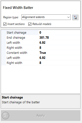

Variation Input Summary
Below is a summary of specific inputs for each Variation, excluding the standard start/end extents inputs:
| TYPE | VARIATION | INPUTS | DESCRIPTION |
| Insert Section | Left/Right: specify which side of the CL Before/After: either place it Before a selected Code or else After the last Code (before the batters) Reference Code: pick a Code. Only required if 'Before' selected above New Code: Type in the new code (prefix with L or R pending side) Start Width: Width at Start Chainage End Width: Width at End Chaiange Slope/Vertical: Specify whether the Code is defined by a slope or a height difference Start Slope/Vertical: Type in start slope/height End Slope/Vertical: Type in end slope/height |
Inserts a new Code into the cross section. Can be before a selected code or at the end (before the batters) AKA 'Insert Section' in the Design Data form |
|
| Insert Section and Interpolate Level | Before/After. Specify whether it goes before (closer to CL) the Code or after Code: New Code will be inserted relative to the position of this Code New Code: Type in the new code (prefix with L or R pending side) Method. Sets how the position is determined. Options: - Relative to Code: Type a value as an offset from the reference Code - Fixed Distance. Type in a distance (measured from the centreline) - Use Alignment: Use an alignment for the New Code offset Offset: If Relative to Code or Fixe Offset Method selected, value will be used Alignment: if Use Alignment Method selected, then the selected alignment will be used. |
Inserts a new Code into the cross section. The inserted Code does NOT affect the top surface shape (not a grade break). AKA 'Insert Section with Interpolated Levels' in the Design Data form |
|
| Insert Section and Match to Surface | New Code: Type in the new code (prefix with L or R pending side) Insert after Code: Insert after a Code in the cross section Surface: Select a surface for the elevaiton of the New Code Alignment: Select an alignment for the New Code offset Height Adjustment: Specify an elevation above/below the Surface |
Inserts a new Code into the cross section and adopts the Surface elevation. Alignment can be used for horizontal position. AKA 'Insert Section & Match Code Levels to Surface' in the Design Data form |
|
| Delete Section | Code: Code to delete | Deletes a Code from the cross section. Next outside Code joins into where the deleted code joined. AKA 'Delete Section' in the Design Data form |
|
| Delete Sections behind Code | Left Code: Delete all codes (except for batters) left of this code Right Code: Delete all codes (except for batters) right of this code |
Select a left and right Code. All sections (excepting batters) outside of these Codes will be deleted. AKA 'Delete All Sections Outside Selected Codes' in the Design Data form |
|
| Delete Sections Conditionally | Trigger Code: Code that must exist and not be inside (closer to CL) of the Code to check Delete if this code: Code to check condition for deletion Condition 1. First condition that must be met for the deletion to occur. Options: - Cut Greater Than: Must have cut larger than the value specified - Cut Less Than: Must have cut less than the value specified - Fill Greater Than: Must have fill larger than the value specified - Fill Less Than: Must have fill less than the value specified - Always: Unconditionally accept this condition as met Value 1: value to check that conditions are met And/Or. Optionally set a second condition to check, or No Second Point for only one condition to check Delete if this Code: as above but for a second condition Condition 2: as above but for a second condition Value 2: as above but for a second condition Delete from Code: Delete from this code to the next code Delete to Code: Delete from previous Code to this code |
Set cut/fill depth rules at a Code to delete one or more Codes in the cross section. AKA 'Conditionally Delete Sections in the Design Data form |
|
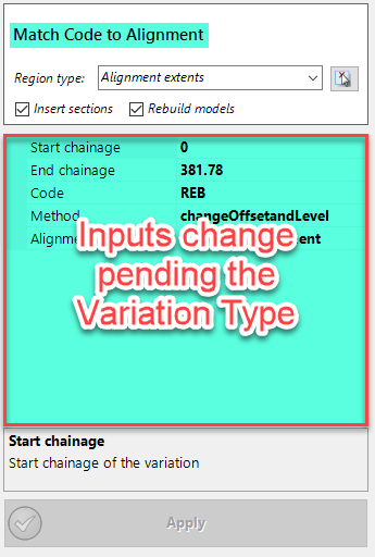
| Match Code to Alignment | Code: code to edit offset Method: Options are: - Change offset and Level. Keeps the slope constant as the width changes - Change Offset Keep Level. Maintains the height difference to the previous code as the width changes Alignment: Select the alignment to use for the Code offset |
Change the offset of a Code to match an alignment AKA 'Set Code Offset to Alignment' in the Design Data form |
|
| Match Code to String | Code: code to edit offset and elevation Method: Options are: - Change offset and Level. Adopt both the elevation and offset position of the string - Hold Level Change Offset. Maintains the height difference to the previous code and uses the string offset - Hold Slope Change Offset. Maintains the crossfall and changes offset to match the string elevation - Hold Offset Change Level. Maintains the offset to the previous code and uses the string elevation - Hold Offest and Level. Does nothing... String: Select the String to use for the Code position |
Change the Elevation and/or Offset of a Code to adopt the position of a String AKA 'Set Code Offsets &/or Levels to String' in the Design Data form |
|
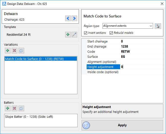
| Match Code to Surface | Code: Code to edit Surface: Surface for Code elevation Alignment (optional): Pick an alignment to set the code offset Height Adjustment: Type a height for the Code above/below the surface elevation Inside Code (Optional): Maintains relative heights between the Code being edited and this Code (maintain relative shape from the Code inwards toward the centreline) |
Set the elevation of a Code to reference a surface (exactly match surface elevations with a raise/lower amount optional. AKA 'Set Code Levels to Match Surface' in the Design Data form |
|
| Match Section Slope to Surface | Code: Code to edit Alignment: Alignment for the code offset Calculate from Surface. Options are: - At End of Section: adopt surface slope at end of the section - At Start of Section: adopt surface stlope at start of the section - Between Section Start End: calculate average surface slope between start and end of the section - Between CL and Section End: adopt the section slope located midway between the centreline and the Code - Midway Between Section Start End: adopt surface slope midway in the section |
Set the design crossfall (slope) of a section to reference the surface crossfall AKA 'Alignment Slope and Offset' in the Design Data form |
|
| Vary Section Slope and Width | Code: Code to edit Set/Increment. Options are: - Set: Type in a fixed width - Increment: Add/Subtract to/from the current width Start Width: Type in a value to set or increment End Width: Type in a value to set or increment Set/Increment. Options are: - Set: Type in a fixed slope/height - Increment: Add/Subtract to/from the current slope/height Start Slope: Type in a value to set or increment End Slope: Type in a value to set or increment |
Change the Code width and slope/height over a chainge range (linearly changing between start and end) AKA 'Linearly Vary Section Slope &/or Width' in the Design Data form |
|
| Copy Codes | String to Copy From: Select String to match Code offset/elevation to Copy Method. Options: - Full Position: Adopt both offset and elevation from selected codes - Just Level: Adopt elevation only from selected codes Code (edit code): Code on the Current String to edit Code (reference code): Code on the reference String to match to [6 Codes allowed per entry] |
Set Code/s on the current String to adopt the Elevation and Offset position of Code/s on a different String AKA 'Copy Codes in the Design Data form |