Sight Distance
Icon:
![]()
Ribbon: Model Viewer > Analysis Tab > Sight Distance
Introduction
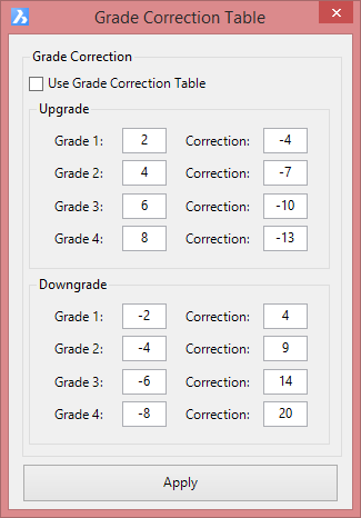
Model Viewer contains some very impressive tools to calculate sight distances along a road and at intersections to ensure minimum design standards are met. Users can create their own sight criteria styles where parameters such as eye height, target height, and minimum sight distance lengths are specified. A grade correction table can also be setup to adjust the minimum sight distance based on the vertical grades along the road.
Visible and obstructed sight lines are displayed in Model Viewer and can be exported out as polylines into CAD.
When design changes are made to a road, the sight distance tools will update automatically when the auto update option is turned on. This allows the designer to check the suitability of a design as soon as vertical or horizontal changes are made to the road.
Ribbon Tab and Navigation
This command forms part of the following tab:
![]()
Information on navigation in the Model Viewer 3D environment is available when reviewing the Model Viewer command help.
Details
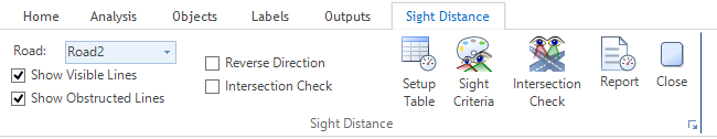
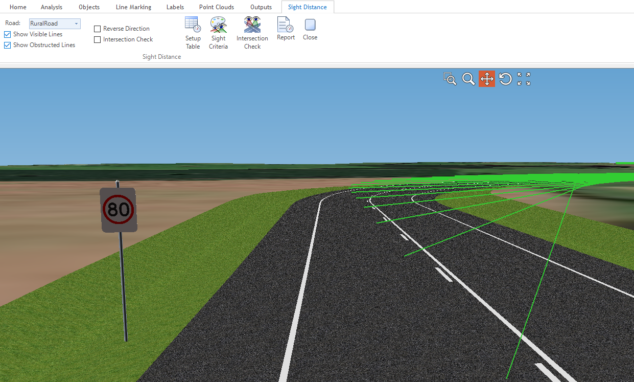
Once the Sight Distance command is selected, a separate tab on the ribbon is displayed, with command inputs as follows:
|
|
|||||||||||||||||||||||||||||||||||||||||||||||||||||||
|
Road |
Pick list of roads in the project to display sight lines for. A message will display if no sight distance controls have been applied using the Setup Table form | ||||||||||||||||||||||||||||||||||||||||||||||||||||||
|
Show Visible Lines |
Toggle on/off the display of visible sight lines | ||||||||||||||||||||||||||||||||||||||||||||||||||||||
|
Show Obstructed Lines |
Toggle on/off the display of obstructed sight lines | ||||||||||||||||||||||||||||||||||||||||||||||||||||||
|
Reverse Direction |
Reverse the direction of the sight distance analysis | ||||||||||||||||||||||||||||||||||||||||||||||||||||||
|
Intersection Check |
Applies sight distance lines for the intersection. The user will be required to setup an intersection check using the Intersection Check command (see below). | ||||||||||||||||||||||||||||||||||||||||||||||||||||||
|
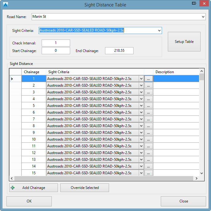
Setup Table |
This command allows users to setup a sight distance check
for a specified road. The user can specify different
sight criteria styles at certain locations along the
road. A form will display with inputs as follows:
|
||||||||||||||||||||||||||||||||||||||||||||||||||||||
|
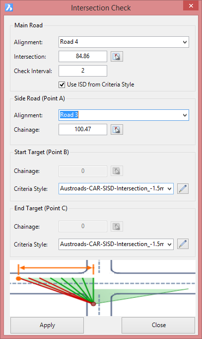
Intersection Check |
This command analyses sight distance at an intersection.
A form will display with inputs as follows:
|
||||||||||||||||||||||||||||||||||||||||||||||||||||||
|
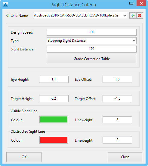
Sight Criteria |
Establishes how the sight distance should be applied, as
well as setting colours for visible and obstructed lines.
A form will display with inputs as follows:
|
||||||||||||||||||||||||||||||||||||||||||||||||||||||
|
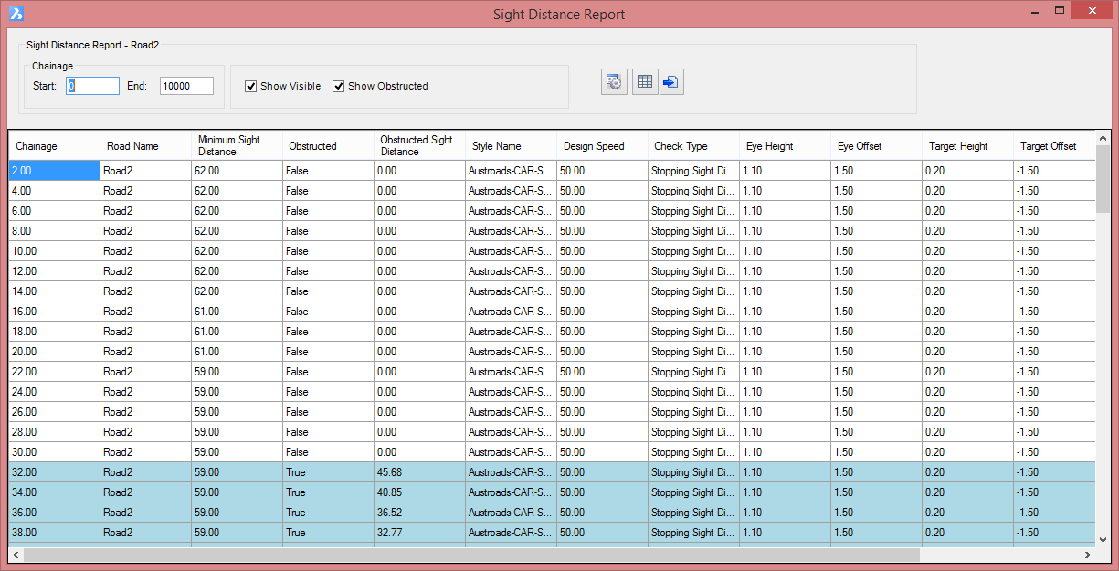
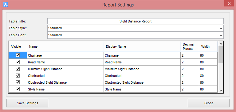
Report |
Users have the option to display the results of the sight
distance check in a table format. This table will update
dynamically as the sight distance command is computed. All
information regarding the sight lines used as part of the
compuation are listed, Users can filter the list by
specifying a chainage range and the display of visible and
obstructed sight lines can be toggled on/off. The report can
be outputted to a table in CAD or a CSV file. Once selected, the following form will display
|
||||||||||||||||||||||||||||||||||||||||||||||||||||||
|
|
Close the sight distance tab. Once this tab is closed, the sight distance check will no longer automatically update when Model Viewer is refreshed. | ||||||||||||||||||||||||||||||||||||||||||||||||||||||