Auto Kerb Returns
Icon: ![]()
![]()
Menu: Roads > Auto Creations Tools > Auto Kerb Returns...
Ribbon: Roads Tab > Design Panel > Kerb Return Drop-down > Auto Kerb
Returns...
Introduction
This command undertakes the following tasks automatically:
- Scans the drawing for all intersection Main and Side Roads (defined from alignments with prefix r- in the description and created by Civil Site Design using the
 Create/Edit Roads or
 Auto Create Roads commands)
 - Locates the edge of each road (by reading the Label from the road cross sections assigned as the connection point in the
 Active Drawing Settings form)
 - Creates alignments of a specified radius to match to the edge of the Main and Side Roads and maintain tangency relative to the Road centerline alignment, using Civil 3D styles set by the designer
- Automatically generates a Kerb Return road object. The Design profile matches the incoming and outgoing levels and grades and includes parabolic vertical curve/s through the kerb return to form a smooth profile.
The designer can control the default radius assigned to the kerbs at the time of running the command and also from the
![]() Active Drawing Settings.
Active Drawing Settings.
This command assumes that the Roads have been created (not necessarily the final designed profile).
Once the kerb returns have been created users can:
- Edit the profile of the kerb returns by changing the profile of the Main and/or Side roads via the
 Create/Edit Roads command
 - Change the automatic redesign options for the kerb return/s by editing the
 Kerb Design Controls
 - Change the radius of any kerb return using the
 Create/Edit Kerb Return command
Details
After starting this command the Designer may need to (if not already defined in the
![]() Active Drawing Settings - Styles tab):
Active Drawing Settings - Styles tab):
- Select the required Civil 3D style for the kerb alignments
- Select the required Civil 3D labels style for the kerb alignments
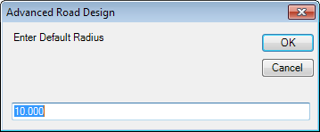
Upon selecting Auto Kerb Returns the following form is displayed:
 |
|
| Enter Default Radius | Type in the required default radius to be applied to all kerb returns that have not already been created. |
| OK | Apply value as the default radius. |
| Cancel | Exit command without creating kerb returns. . |
Note: Before running this command, designers can create single radius
or 3 centered radius kerb returns at selected intersection locations using the
![]() Create/Edit Kerb Return
command. This command also enables the user to create a kerb return from a
manually created alignment (the alignment must be created with description
prefix k-)
Create/Edit Kerb Return
command. This command also enables the user to create a kerb return from a
manually created alignment (the alignment must be created with description
prefix k-)
The command is fully automated - the software includes it's own algorithm for locating the connection points on the main and side road corridors at the edge of each road, using the road centerline for directions start and end.
Note: Given the iterative nature of the command, designers should provide Road lengths in any direction from the intersection point to be AT LEAST three times the radius of the kerb return to provide the software with a reasonable starting point to iterate from.
After Running the Command:
 |
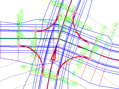
Alignments are created to connect the edge of the Main and
Side Roads at every quadrant.
All kerb return alignments created with this command will have the same radius. This occurs for ALL intersecting Roads in the drawing (where those Roads have been created from alignments prefixed with r- in the Description). In the example shown the thick red lines represent the Civil 3D alignments created by the software. Use the
|
For more information regarding the kerb return controls please review the
![]() Create/Edit Kerb Return command.
Create/Edit Kerb Return command.