Auto Create Corridor
Icon: ![]()
![]()
Menu: Roads > Civil 3D Outputs > Auto Create Corridor
Ribbon: Roads Tab > Modelling Panel > Auto Create Corridor
Introduction
During the design process in Civil Site Design, or after design is complete, the Designer can use this command to automatically generate a single Civil 3D corridor of the road networks, including all intersection match-in and trimming.
After creating the corridor, simply re-run this command (or use the Civil 3D options to rebuild the corridor) to update it with the latest changes made in Civil Site Design.
To create the corridor the Designer needs to:
- Undertake a road design with Civil Site Design, including (if required) Kerb Returns, Cul-de-sacs and Knuckles
- Create one single assembly in Civil 3D with the name 'CORRIDOR-EZY' and applying the CSD Super Subassembly (or cadappsBasicLane) on the left and right side. Click here for more information on creating an appropriate assembly
- Ensure that the Create Corridor Command Settings do not have tangent, curve, spiral or profile curve sampling (all these should be set to zero) and all geometry points set to No - see below for a description
- Run this command to create the corridor AND the Civil 3D profiles in the drawing
The ![]() Create/Update Civil 3D Profiles command can be optionally run before the Auto Create Corridor command if it is desired to review the profile designs outputted from Civil Site Design into Civil 3D before building the corridor.
Create/Update Civil 3D Profiles command can be optionally run before the Auto Create Corridor command if it is desired to review the profile designs outputted from Civil Site Design into Civil 3D before building the corridor.
A single corridor will be created with multiple baselines for each road object (road, kerb return, cul-de-sac and knuckle) using the Civil Site Design assembly. Designers are encouraged to augment the corridor with additional regions and additional baselines comprising 'standard' assembly configurations.
Details
This command will output the design information from Civil Site Design to create a single, multiple baseline, corridor in Civil 3D complete with intersection trimming.
The command works by processing the Civil Site Design design data through a single Civil 3D Assembly which comprises the 'CSD Super Subassembly (or cadappsBasicLane) on the left and right side.
At the time of running the command, every profile designed within the software will be inserted into the drawing as a Civil 3D profile and then be used to build the corridor. If the profiles already exist in the drawing, they will be updated.
To update the corridor after adding extra roads, simply re-run this command. After adjusting the profile designs inside Civil Site Design, simply use the corridor rebuild utilities inside Civil 3D.
Prerequisites
Before running this command the Designer must first:
- Undertake a road design with Civil Site Design, including (if required) Kerb Returns, Cul-de-sacs and Knuckles
- Create one single assembly in Civil 3D with the name 'CORRIDOR-EZY' and applying the CSD Super Subassembly (or cadappsBasicLane) on the left and right side.
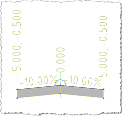
An example is shown below:
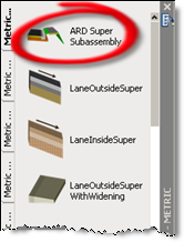
To add the subassembly to the tool pallette, from the Civil 3D Ribbon:
Insert Tab > Import Slideout > Import Subassemblies.
Navigate to the CSD Settings folder (use the command in the General tab to open and confirm path). Select file CSD-Corridor-20XX.pkt file.
It is critical to this command that the 'Civil Site Design' assembly already exists in the drawing.
If desired, the ![]() Create/Update Civil 3D Profiles command can be run before the Auto Create Corridor command to output the profiles from Civil Site Design and create Civil 3D profiles in the drawing.
Create/Update Civil 3D Profiles command can be run before the Auto Create Corridor command to output the profiles from Civil Site Design and create Civil 3D profiles in the drawing.
Command Outputs
After running the command the software will process the profiles along each alignment and feed in the cross section design through the Civil Site Design assembly in the drawing (which is created by the Designer - see above) to generate a Civil 3D corridor of the entire road network designed.
A corridor is created in the drawing and is included in the Civil 3D Toolspace:
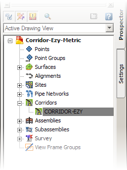
The outputted corridor is named 'CORRIDOR-EZY'.
Running the command again will update the 'CORRIDOR-EZY' Civil 3D corridor in the drawing - if none exists with that name then the software creates a corridor.
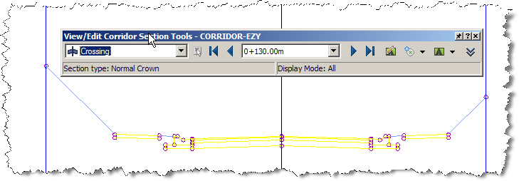
An example corridor outputted using this command is shown below:
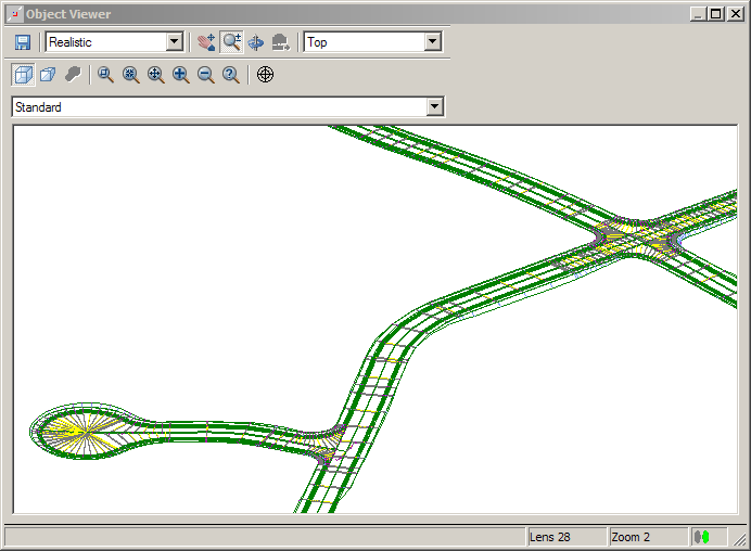
This is a multi-baseline corridor in Civil 3D.
Designers can review the properties of the corridor as per standard tools in Civil 3D. One method is to right-click the corridor in Toolspace and click Properties, as shown below:
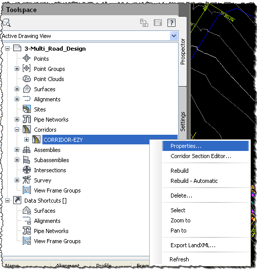
The following form is displayed:
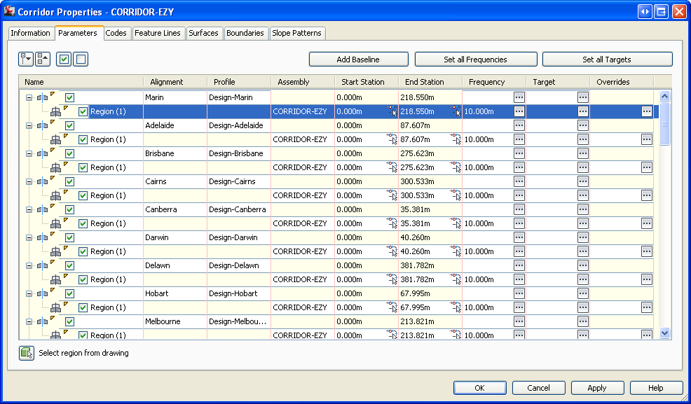
The corridor is made up of:
- A baseline for each Road Object (Road, Kerb Return, Cul-de-sac or Knuckle)
- A single region for each baseline, using a Civil 3D design profile generated by the software and the 'Civil Site Design' assembly
Designers can always use the Split Region command within the above form to insert a region within the corridor. This may be desired when users wish to manually override the software outputs and utilise a standard Civil 3D assembly in certain sections.
Designers can also add extra baselines as desired.
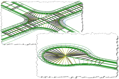
As shown in the design process, the road section of the Kerb Returns, Cul-de-sacs and Knuckles are extended into the intersection zone (to the edge of travelled way and/or the Road centerline) to form an integrated road network with continuous road areas. This method ensures a higher level of accuracy in volume outputs.
Special Note: The software uses a specific naming convention for the profiles it includes in the Civil 3D corridor it creates. If Designers adjust the name, it is likely that running this command will add in a new design profile with the preferred name required by the software.
Setting Corridor Sampling Frequencies - Automatically added by Civil Site Design
Designers are advised to NOT have the Corridor creation process add any Sampling for the Corridor - Civil Site Design will add all the corridor sample points based on the sampling added in Civil Site Design for the CSD Objects.
To set up the system to prevent unwanted sampling, designers should:
-
Click on the Settings Tab in the Civil 3D Toolspace
-
Navigate to Corridors and Expand this. Expand Commands and then double click on Create Corridor to edit it
-
Establish the Assembly Insertion Defaults as follows:
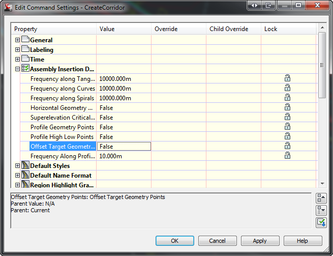
The sampling frequency is set by the Civil Site Design software. It can be edited if required and the corridor rebuilt, however the software automatically adds sampling frequencies at all the intersections and relevant feature locations.