Crossing Pipes
Details
This provides for the ability to display crossing pipes. Both a representation of the pipe (crossing pipe section and/or longitudinal pipe extents) and text can be applied.
For circular pipes, an ellipse will display representing the crossing pipe dimensions and angle of crossing.
The information is entered via a multi-tabbed form.
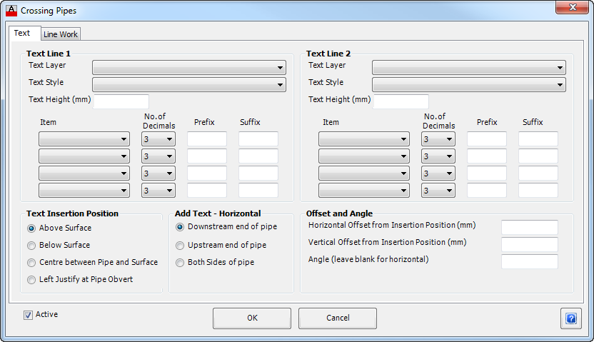
Upon selecting the Crossing Pipes button from the Data Bands/Controls form the following form is displayed:
Text Tab
Controls the text used for the band.
|
|
| Text Line 1 | Up to two lines of text can be used to describe the crossing pipe. This items selected here will appear on the first line. |
| Text Layer | From the drop down list select the required layer for the first line of text. Use the Layer Settings command to edit the layers available. |
| Text Style | From the drop down list select the required style for the Text. |
| Text Height (mm) | Enter the size of the band Text in millimetres. |
| Item | From the drop down list select an item to be used to describe the crossing pipe. Up to four items can be included - the text will be appended together into a single line text string.
Selectable items include:
|
| No. of Decimal Places | From the drop down list select the number of Decimal places to display for the item, either 0, 1, 2 or 3, if applicable. |
| Prefix | Enter an optional Prefix to be added to the item in the box provided. Note: Use an _ (underscore) as the first or last character to represent a space - the _ (underscore) is replaced with a space in the output. |
| Suffix | Enter an optional Suffix to be added to the item in the box provided. Note: Use an _ (underscore) as the first or last character to represent a space - the _ (underscore) is replaced with a space in the output. |
| Line 2 | Up to two lines of text can be used to describe the crossing pipe. This items selected here will appear on the second line. Refer Line 1 (above) for details. |
| Insertion Position - Vertical | Provides control over the vertical position of the text. |
| Above Surface | Places text above the surface line work. |
| Below Surface | Places text below the surface line work. |
| Centre between Pipe and Surface | Centres the text between the Crossing Pipe Obvert and Surface line work. |
| Left Justify at Pipe Obvert | Places the left justified text at the Crossing Pipe obvert. |
| Insertion Position - Horizontal | Provides controls for the horizontal position of the text when pipes are running close to parallel. This text is in addition to the cross point text. For parallel pipes that are displayed, both the upstream and downstream ends can be reported. |
| Downstream | Places text on the downstream side of the crossing pipe. |
| Upstream | Places text on the upstream side of the crossing pipe. |
| Both Sides | Places text on both sides of the crossing pipe. |
| Offset and Angle | Provides additional control over the text position and orientation. |
| Horizontal Offset from Insertion Position | In the box provided enter an offset for the text to displaced from the Insertion Position. |
| Vertical Offset from Insertion Position | In the box provided enter an offset for the text to displaced from the Insertion Position. |
| Angle | In the box provided enter an angle for the text. If the box is left blank, the text will be plotted horizontal. |
| Active | Tick this box to make this item active and the information will be plotted. This is ticked on by default. This provides a quick way to turn this item on and off, rather than deleting the item from the list. |
| OK | Apply, exit the form and add the crossing pipes to the display. |
| Cancel | Exit the form without making any changes. |
LineworkTab
This controls the layer used to present the crossing pipe objects.
 |
|
| Layer | From the drop down list select the required layer for displaying the crossing pipe/s. Use the Layer Settings command to edit the layers available. |