String Vertical Geometry Labels
| Menu: | Via Label Plan |
| Ribbon: | Via Label Plan |
Introduction
This command adds labels to the plan drawing at various vertical geometry locations, as designed. The command is intended for any design string, to supplement alignment labelling (which labels horizontal geometry only).
VC Label Geometry
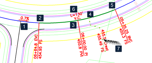
Vertical Geometry details:
- Vertical tangent
- Start of vertical curve
- Point of vertical intersection (IP)
- High/Low point
- End of vertical curve
- Vertical curve details
- Users are able to set up Label Styles to include lines (polylines) and to set the text position relative to the polyline. Grip edit of the polyline will result in repositioning of the text. Refer to the Label Styles command for information on associating text elements in a Label Style to line (polyline) elements.
Label presentation is up to the user, via creation and application of Label Styles. Each label can consist of any arrangement of symbols (blocks), lines (polylines) and text. Different label styles can be assigned to each vertical geometry type.
Label Editing
Label insertion positions (as determined by the label 'marker') will be set by the vertical geometry.
Lines (polylines) are able to be set to start from different vertical geometry positions, as set in the Label Styles.
Each object that forms part of the Label Style can be moved and/or rotated in the drawing, however the label 'marker' will always be set to match the vertical geometry to which it belongs. Text objects can be associated with the Line (polyline) geometry, making is easy to resolve overlapping text by grip editing the polyline component of the label.
Updating Labels
Labels are always updated Add Labels button is pressed on this form.
Otherwise, if the vertical geometry is edited, the Label ![]() Synchronise command should be used to update all VC Labels in the drawing.
Synchronise command should be used to update all VC Labels in the drawing.
The ![]() Synchronise command should also be used if the Label Style/s of the labelled objects has been edited.
Synchronise command should also be used if the Label Style/s of the labelled objects has been edited.
About Text Heights, Symbol Sizes and Line Lengths
It is recommended that all text heights, symbol sizes, offsets and line lengths be specified in mm (or in imperial situations, inch) units. When Labels are inserted into the drawing, users can specify a drawing scale to apply to the labels upon insertion (or set the labels to automatically react to the drawing annotation scale). The scale is applied to all values for the geometry, size and position of all components of the label.
Details
These are created via the Label Plan command. If new, users will need to firstly name the group. The followng form displays:
|
|
|||||||||||||||||||||||||||||||||||||||||||||||||||||||
|
Plot (Label Set) Name |
Name of the currently selected label set (not editable). |
||||||||||||||||||||||||||||||||||||||||||||||||||||||
|
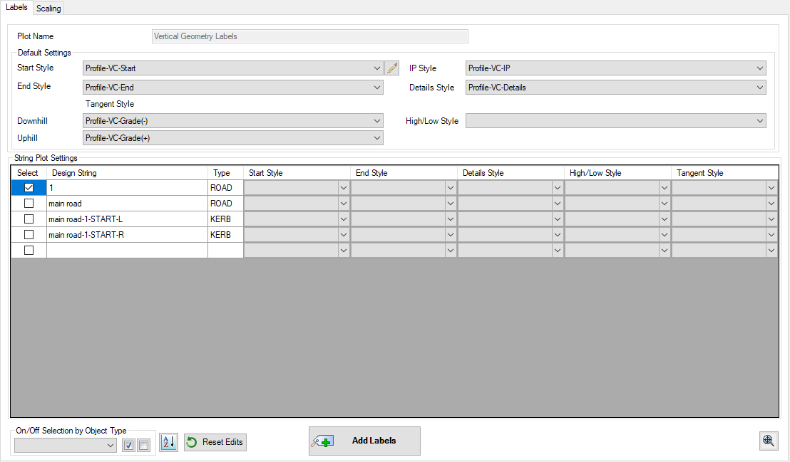
Labels Tab |
|
||||||||||||||||||||||||||||||||||||||||||||||||||||||
|
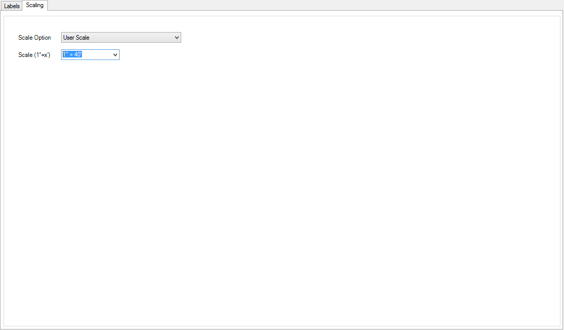
Scaling Tab |
This tab manages the scaling of the labels within the drawing |
||||||||||||||||||||||||||||||||||||||||||||||||||||||
|
|
|
||||||||||||||||||||||||||||||||||||||||||||||||||||||
| Close | Close the form | ||||||||||||||||||||||||||||||||||||||||||||||||||||||
| Cancel | Cancel actions on the form and close. | ||||||||||||||||||||||||||||||||||||||||||||||||||||||
| Pan and zoom in the drawing using the middle mouse button. Press any key or left click the mouse button to return to the form. | |||||||||||||||||||||||||||||||||||||||||||||||||||||||