Reference Profiles (Reference Strings)
Icon: |
Introduction
The Reference Profiles command simplifies the design of road edges or curbs (or any Code included on a Road String) by dynamically referencing the road centerline design. This tool allows for quick creation of road crossfall transitions, ensuring that the longitudinal grades of left and right curbs meet design requirements.
The Reference Profiles command acts as a central interface, providing complete control over curb design, Road centreline reference ranges, centerline elevation relationships, and projection onto main road profile views.
From the Reference Profiles command, users obtain access to the Vertical Grading Editor to edit the vertical design, Project Profiles command and Create/Update Civil 3D Profiles command.
Key Features
-
Dynamic Reference to Road Centerline: Reference profiles can be added to any model containing road strings. The centerline design, including vertical IPs and curves, is copied, and the elevation relationship between the centerline and reference profiles can be controlled within specific ranges.
-
Intersection Connectivity: You can specify an intersection match code to ensure proper alignment of curb or edge of road profiles with the main road.
-
Vertical Grading Editor Access: The command provides direct access to the Vertical Grading Editor for curb line design. It also includes design aids like centerline elevation displays and crossfall projections.
-
Editing Road Cross Sections: The Reference Profile elevations can be used directly to edit the cross sections of the Main Road. A Custom Variation can be applied (included in the software) to edit the requested Code and maintain the relative position of an inside code (for example, users could apply the Reference Profile elevations to the back of kerb, and maintain relative position of the lip of kerb to maintain the kerb shape)
-
Auto Create Functionality: This feature enables fast creation of reference profiles for all roads. You select the roads needing reference profiles, the relevant codes from the road being redesigned, and have the option to immediately create profiles output to Civil 3D.
-
Create/Update Process: After making changes to a reference profile, clicking the Create/Update button applies the changes to road cross sections. The entire road network model will be rebuilt in this process.
-
Integration with Civil 3D:Reference profiles can be projected onto Civil 3D road profile views (Projected Profiles) and updated when the Create/Update Rerence Profiles button (on this form) is selected. The Projected Profiles form can also be used to create Projected Profiles for road alignments.
-
Toolspace Access: Reference Profiles can be accessed via the Toolspace via right click on the Road Strings, Profile Strings collection.
Reference Profiles can also be updated from the Tooslapce by clicking on the Sync button
Reference Profiles adopt the same alignment geometry as the Road Centreline they are referenced to.
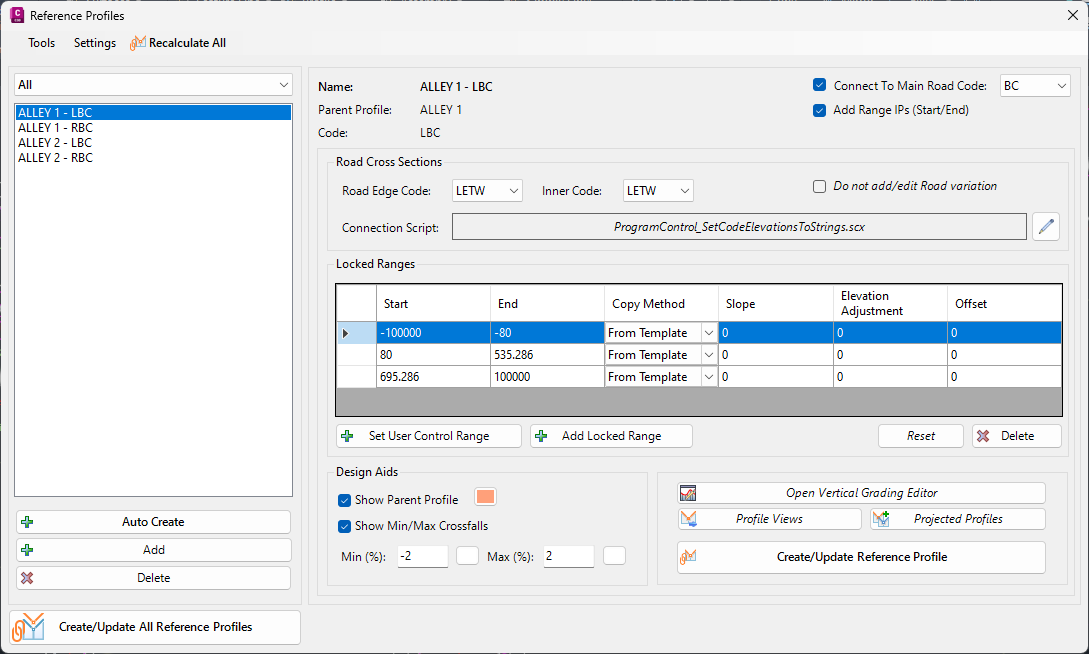
Interface Overview
The Reference Profiles form is divided into two core parts:
-
Left Side panel
-
From the left side users created Reference Profiles that reference a road centreline. Any Code can be set up as a reference.
-
Reference profiles can be added automatically, singly, and deleted and all uptated
-
-
Right Side panel
-
This sets out the controls for the selected Reference Profile including:
-
Reference Code to associate with for the Road String
-
Chainage Ranges over which to 'lock' the Reference Profile design to match the centreline. Over these ranges, the Reference Profile will adopt the same IP's and vertical curves as the road centreline, At the extents of each 'lock' region, an IP will be added to the vertical design (unless the Road centreline has a vertical curve applied at that chainage)
-
Addition of a design IP that matches the Main Road edge code (selected by the user). Usually this will be the same Code as the Code used by the Reference Profile
-
Defining how to calculate the relative elevation at each IP. This can be read from the Template/s applied or by inputing a Slope, Elevation Adjustment and Offset. In the case of specifying using a slope and elevation adjustment, the user specifies the Road Edge Code used to calculate the position of the Reference Profile Code
-
Connection of the Reference Profile elevations to the cross sections of the Main Road, including any inner code set to maintain the relative position and shape
-
Addition of design constraints (Design Aids) to display the road centreline elevations and a slope projection from the Road centreline (this is based on the cross section widths set at the start of the Road.
-
-
Operational Controls - Intersection Matching, Locking Ranges, Editing Cross Sections and Design Aids
This command is purpose built to facilitate design of left/right sides of a Road that allows users to:
-
Set ranges over which to copy information from the CL, and ranges over which to enable user editing
-
Include the intersect of the code with the Main Road as a design IP
-
Apply the new Reference Profile String as a Variation to the Parent String, to adjust the cross sections
Here is a screen shot of the command applied to a Road, where a Reference String is being used to describe the left edge of the road pavement:
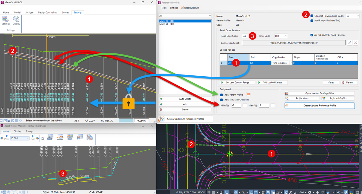
-
The Locked Ranges set up the ranges along the Reference Profile where it is required to copy the design of the Parent Profile String. Users can set the Copy Method for calculating elevation adjustments relative to the Parent String centreline. Note on the Profile View that a design IP is also created at the start (as well as the end) of the Locked Range. This elevation calculates the Profile String design at that chainage. These start/end range IP's can be omitted using the tick box top right
-
The Reference Profile can include a design IP matching a Code on the Main Road cross section to control the intersection. This uses the calculated cross section widths of the Parent Profile String for the selected code and finds the intersection with the Main Road cross section code
-
The Reference Profile can be directly applied to the selected Code to edit the cross sections. Note that users can design with a code representing an outer code (eg: Back of Kerb) and maintain the relative position to an inner code (eg: Lip/Edge of Kerb) using the Reference Profile inputs. This is managed by applying Custom Variation/s to the Main Road.
Design and Updating
When updating the design in the Vertical Grading Editor, users will see this additional command in the Home Ribbon tab:
![]() Clicking this button opens to this command.
Clicking this button opens to this command.
After updating the vertical design it is important to force an update to the Road cross sections. This can be done via a number of methods:
-
Running Create/Update All Reference Profiles from this form
-
Clicking on the Sync/Update button on the Toolspace
-
Running a thread that recomputes all strings and rebuilds all models
Details
Upon selecting the command the following form is displayed:
|
|
|||||||||||||||||||||||||||||||||||
|
Menu Controls |
These command controls apply to all Reference Profiles | ||||||||||||||||||||||||||||||||||
|
Tools > |
Creates all kerb returns at all intersections, using the settings applied at each kerb return. | ||||||||||||||||||||||||||||||||||
|
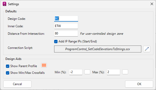
Settings |
|
||||||||||||||||||||||||||||||||||
|
Recalculate All |
Recalculates all Reference Profiles including updating network strings, surfaces and Civil 3D Profiles | ||||||||||||||||||||||||||||||||||
|
Reference Profiles Panel |
Lists all Reference Profiles in the project | ||||||||||||||||||||||||||||||||||
|
[Filter dropdown] |
Show all Reference Profiles or select to show Reference Profiles created for a single Road | ||||||||||||||||||||||||||||||||||
|
[List of Reference Profiles] |
Lists all created Reference Profiles | ||||||||||||||||||||||||||||||||||
|
Auto Create |
Click to create multiple Reference Profiles in the same action.
|
||||||||||||||||||||||||||||||||||
| Add | Click to pick a kerb return from the drawing to edit | ||||||||||||||||||||||||||||||||||
| Delete | Click to pick a kerb return from the drawing to edit | ||||||||||||||||||||||||||||||||||
|
Crossing Intersection Panel |
Create, edit and manage individual cross sections from this panel | ||||||||||||||||||||||||||||||||||
|
Main Road: |
Lists the main road for the intersection. For Tee intersections, this cannot be altered. | ||||||||||||||||||||||||||||||||||
|
Side Road: |
Lists the side road for the intersection. For Tee intersections, this cannot be altered. | ||||||||||||||||||||||||||||||||||
|
|
Click to switch the main and side roads in the intersection. For Tee intersections, this cannot be altered. | ||||||||||||||||||||||||||||||||||
|
'T' Intersection Panel |
For crossing roads, users can set the intersection to be converted to a Tee type intersection | ||||||||||||||||||||||||||||||||||
|
Type |
Set the Type of intersection to form at the crossing: - None: maintain a full cross road intersection - Remove Start Returns. Removes the 'Start' kerb returns to form a tee - Remove End Returns. Removes the 'End' kerb returns to form a tee |
||||||||||||||||||||||||||||||||||
|
|
Click to apply the change in intersection Type For Tee intersections, this cannot be altered. |
||||||||||||||||||||||||||||||||||
|
Intersection Controls |
Sets the kerb returns and intersection controls for the selected intersection | ||||||||||||||||||||||||||||||||||
|
Create > Create/Update Kerb Returns |
Creates all kerb returns for the selected intersection as per the kerb return settings for that intersection | ||||||||||||||||||||||||||||||||||
|
Edit > Override Default Radius |
Click to set a single radius to apply to all kerb returns for the intersection | ||||||||||||||||||||||||||||||||||
|
Edit > Override Connection Controls |
Click to set the Connection Code to apply to all kerb returns for the intersection. This sets the Code that the kerb returns match to vertically and horizontally | ||||||||||||||||||||||||||||||||||
| Edit > Override Templates | Click to set the Template to apply to all kerb returns for the intersection. | ||||||||||||||||||||||||||||||||||
| Edit > Set Returns to Remove Main Road Edge | Click to set all kerb returns for the intersection as All-Crowned (main road edge removed). | ||||||||||||||||||||||||||||||||||
| Edit > Set Returns to Keep Main Road Edge | Click to set all kerb returns for the intersction as Primary Crowned (main road ege maintained through the intersction) | ||||||||||||||||||||||||||||||||||
| Edit > Toggle ON Create Returns | Click to set all kerb returns to be created in the intersection. | ||||||||||||||||||||||||||||||||||
| Edit > Toggle OFF Create Returns | Click to see no kerb returns to be created in the intersection. | ||||||||||||||||||||||||||||||||||
| Delete > Delete Return | Deletes the currently selected Kerb Return. | ||||||||||||||||||||||||||||||||||
| Delete > Delete All Returns | Deletes all kerb returns created for this intersection. | ||||||||||||||||||||||||||||||||||
|
[Kerb Return Controls] |
Lists each kerb return for editing | ||||||||||||||||||||||||||||||||||
| [Individual Kerb Returns] | Each kerb return is listed in a tab. Kerb rerturn tabs include: End Left, End Right, Start Left, Start Right | ||||||||||||||||||||||||||||||||||
| Create | Toggle on to have the kerb return created when the Apply or Create/Update Intersection commands are run | ||||||||||||||||||||||||||||||||||
| Name | Non-editable field describing the default kerb return name | ||||||||||||||||||||||||||||||||||
| Template | Picklist to select the Template to apply at the kerb return | ||||||||||||||||||||||||||||||||||
| Connection Code | Picklist of Codes from the Roads to use as the horizontal and vertical connection of the kerb return | ||||||||||||||||||||||||||||||||||
| Default Radius | Type in the Radius to apply for this kerb returns. | ||||||||||||||||||||||||||||||||||
| Remove Main Road Edges | Toggle on to convert this intersection quadrant into an All-Crowned type intersection | ||||||||||||||||||||||||||||||||||
| Apply | Click to apply the settings to the kerb return. | ||||||||||||||||||||||||||||||||||
| Edit Kerb Return | Click to open the Create/Edit Kerb Return form for additional geometry controls for the kerb return. | ||||||||||||||||||||||||||||||||||
| Ignore Intersection | Tick on for the intersection to be ignored. This will vertically disconnect the Main and Side Roads to facilitate grade separated design | ||||||||||||||||||||||||||||||||||
| Zoom | Tick on to zoom to an intersection when selected. | ||||||||||||||||||||||||||||||||||
| Zoom value | Type in a zoom value . | ||||||||||||||||||||||||||||||||||
| Zoom to | Click to reset zoom to the current intersection. | ||||||||||||||||||||||||||||||||||
| OK | Save all intersection changes and exit. | ||||||||||||||||||||||||||||||||||
| Cancel | Cancel intersection changes and exit. | ||||||||||||||||||||||||||||||||||